
Teardown Tuesday: Space Heater
In this teardown, we dissect a rotating space heater that has two modes of operation: silence and turbo.
In this teardown, we dissect a rotating space heater that has two modes of operation: silence and turbo.
This is a 120VAC-powered space heater. Actually, according to its manufacturer (Rowenta), this unit is referred to as a whole room ceramic heater.
This particular model (SO9276) does not include a temperature-setting turn dial, but instead it has multiple pushbuttons and two, dual seven-segment LED displays for configuring the desired temperature setting.
Additionally, this unit has an 800W silence mode (which is the low setting) and the 1500W turbo mode (which is the high setting). Regardless of the semantics, this rather sleek-looking device should be fun to rip in.

The heater's front, top, and bottom views. Notice the safety switch located on the bottom side.

The heater's backside, which includes a plastic cover that secures the removable/washable dust filter at the fan's air intake.
Gaining Access
After removing fifteen screws (many more than I was expecting), I was able to separate the heater's enclosure pieces, thus exposing its innards. Surprisingly—although I shouldn't have been that surprised—this unit makes use of many discrete wires (see the image below).
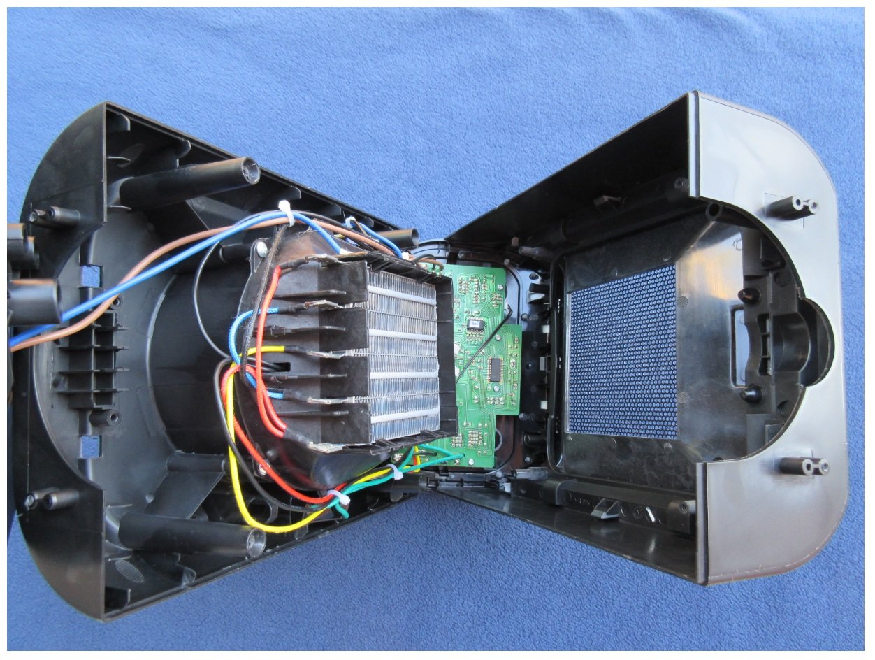
A first glance at the heater's guts.
As can be viewed in the figure below, we can see how the safety switch is connected in series with the 120 VAC line. When activated—that is, for example, when the heater is tipped over—the switch opens its contacts, therefore preventing electricity from flowing to the heater's internal electronics.

The PCB can be seen inside the enclosure.
After removing the unit's remaining screws, all the heater's internal components can be fully extracted from its enclosure (see the following image). Still, however, because most of the wires are either soldered or permanently-crimped to various components, working with this assembly was quite cumbersome. However, this design approach (i.e., not using quick-connect connectors) is most likely very cost effective.

The internal assembly includes PCBs, heating elements, a motor/fan, and wires.
Inspecting the PCBs
At this point, we'll turn our focus to the PCBs; there are two of them.
Main PCB
This primary circuit board contains the vast majority of the electronics found inside this heating unit. The board, itself—a 2-layer design—looks to be well laid out; as I've mentioned in numerous other teardown articles, minimizing the PCB's layer count typically equates to lower material costs. So kudos to the PCB layout person/team for being able to take advantage of a 2-layer board!
In fact, if you look closely at the PCB, you'll notice that all the copper is actually located on only one side of the board... reducing material costs even more. Impressive!

This design is reminiscent of the time when PCBs often used terms such as copper side and component side.
Some of the major components found on this PCB are listed below:
- Off-Line Switcher IC: Part marking LNK564PN
- Transformer: No distinguishable part marking.
- Triac: Part marking 600D BT134. Similar to this triac. These triacs appear to control the fan (motor) speed.
- Heater Relays: Part marking SRD-S-112DM. The relays manage the low- and high-heat level settings.
- Tactile Switch: No part marking, but similar to this switch.
- 2-Digit 7-Segment LED Displays: Part marking E1-2040C5Y3-P25.5. Similar to this one.
- Voltage Regulator: Part marking 79L05.
- Buzzer: no part marking. Similar to this part.
- Bridge Rectifier: Part marking DB105 HY
- Safety Capacitor: Part marking MKP 0.33mF K X2 275VAC
- Microcontroller: Part marking SN8P2722SG
- LED Driver: Part marking TM1628
The following motor start-run capacitor resides external to the PCB, but it's connected to the board via wires.

This fan/motor capacitor is tethered to the PCB.
- Fan/Motor Capacitor: Part marking C61-P2 3uF 5% 250VAC
Thermostat PCB
This PCB uses a transformerless power supply to sound a buzzer when the associated thermostat is activated (opens). This action occurs when the thermostat exceeds its temperature threshold—which looks to be 70°C, according to the part marking. And similar to the main PCB, this board also has copper placed on only one side.

This small PCB contains the overheating audio alarm components, and a transformerless power supply.
- Safety Capacitor: Part marking MKP 474(K) 275VAC X2. Similar to this cap.
- Zener Diode: Part marking 2EZ12D5. Similar to this part.
- Diode: Part marking 1N4007. Similar to this diode.
- Buzzer: Part marking TMB12A05
- Fuse: Part marking T500mA250V. Similar to this fuse.
- MOV (metal-oxide varistor): Part marking 07K271. Similar to this MOV.
- Thermostat: Part marking 125V-16A TP T5/33 70
Heating Elements and the Motor/Fan
Heating Elements
This unit's heating mechanism design—which looks to be the norm among many space heaters—is quite intriguing. It looks like a miniaturized version of my truck's radiator design, which makes sense as they are both designed to dissipate heat.
As can be observed in the figure below, we can see how the two heating elements are connected (using wires) to the main PCB: these are the same yellow and red wires that are connected to the two ("high" and "low") relays.
Out of curiosity, I measured the resistance of the two heating elements; both measured approximately 50 Ω.

The wires are color-coded for the two heating elements.
Motor/Fan
Since this space heater's fan is expected to spin whenever the heater is enabled, it's not unexpected to find a rather robust-looking motor (see image below) for operating the fan.

This stout motor seems up to the task of spinning the heater's fan for years to come.
- Motor: Part marking YJ58-12E-0092, from Keli Motor.
Conclusion
This sleek and easy-to-use—yes, I experimented with it a bit prior to breaking it down—variable-heat-setting space heater (i.e., "whole room ceramic heater") appears to be designed well, assembled nicely, and includes some cost-reduction measures, such as using single-sided (regarding the copper) PCBs.
I was, and still am, somewhat surprised to see the use of a transformerless power supply. But, perhaps, this power supply design approach helps reduce the materials cost of this unit.
Next Teardown: Immersion Cooker


It would be cool if you made some sort of block diagram of these devices based on what you learned from the teardown.