
Controlling a Servo with a PICAXE and an IR Sensor
A PICAXE 08M2 can be used to read the amount of IR (infrared) light falling on a phototransistor and respond by moving a servo to a predetermined position.
Learn how to combine a PICAXE, IR sensors, and a servo motor to create a device that responds to a moving stimulus. Spoilers: I hook it up to eyeballs that can follow a finger.
Related Information
- Servo Motor Control with an Arduino
- Servo Control with Arduino Through MATLAB
- Servo Control via USB with the SAM4S Xplained Pro
- Control a Servo from Your PC with the Atmel SAM4S
What's a PICAXE?
PICAXEs are PIC microcontrollers that have been preloaded with a bootstrap code that allows programming in BASIC language. All About Circuits provides a series of articles that serve as a guide to choosing and using any of the chips in the PICAXE family. This article will provide an excellent starting point and will lead you to other articles in the series.

Project Overview
This project consists of building a circuit using common IR (infrared) LEDs to produce IR emissions and an IR phototransistor to detect reflected IR light. The voltage from the phototransistors varies with the intensity of the IR light received. A specially programmed PICAXE microcontroller converts this analog voltage to a digital format and stores it for comparison with the output from other IR phototransistors.
Based on the relative levels of the IR light, the PICAXE signals a servo motor to rotate to a predetermined position. Thus, reflected IR light can be used to control physical movements.
What's a Servo?
Servos, or more specifically servomotors, are electromechanical devices that consist of (1) an electric motor with an accessible output shaft, (2) a mechanism to determine the rotary position of the output shaft, and (3) electronic circuitry to receive control signals and position the output shaft accordingly.
One of the most familiar uses of small servos is to move the throttle and control surfaces of RC (radio control) airplanes. Servos are available in a variety of sizes, shapes, and capabilities. A servo suitable for use in this project is the Tower-Pro MG996R, two of which are shown in the photo below.

The MG996R servo operates on 4.8V to 7.2V, and can draw from 500 mA to almost a full ampere depending upon its load. The output shaft covers a range of 120 degrees (60 degrees each side of center.) For a more complete description, download and read the datasheet. A little on-line research will produce all the information you can imagine about servomotors.
The IR Servo Controller Circuit
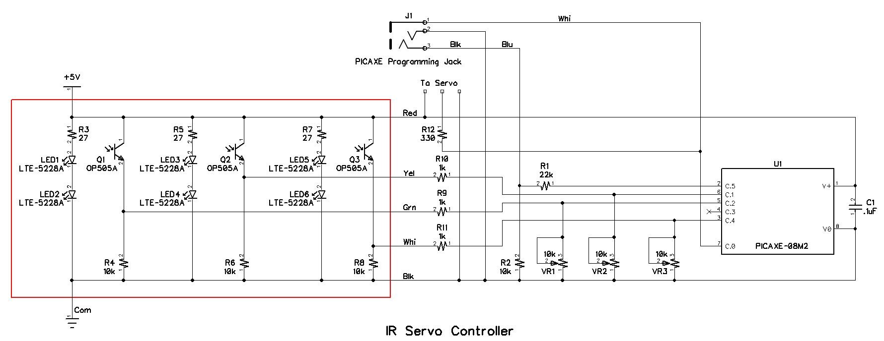
The circuit schematic for the IR servo controller is shown below.
Click to enlarge
Note that there are three identical IR light production and detection subcircuits: the first consists of LED1, LED2, R3, R4, and Q1 (an IR-sensitive phototransistor;) the second consists of LED3, LED4, R5, R6, and Q2; the third consists of LED5, LED6, R7, R8, and Q3. In each of the three subcircuits, the LEDs produce infrared radiation and the phototransistor detects it and produces a voltage at the emitter node. As you see, there is no physical connection to the base of the phototransistor; collector-to-emitter current is controlled by the light received. Thus, the voltage out varies in amplitude according to the intensity of the IR light falling on the phototransistor.
Each of the three output voltages is presented through a current-limiting resistor to one input of U1 (a PICAXE 08M2 microcontroller), where it is converted from an analog to a digital value and stored. The variable resistors VR1 through VR3 are used to balance the voltages and compensate for unequal amounts of ambient light falling on each of the phototransistors; reducing the resistance of the potentiometer reduces the equivalent resistance between emitter and ground, and results in a lower voltage applied to the microcontroller's input pin.
PinC.0 (on leg 7) of U1 is the output for the control signals to the servo. R12 is a current-limiting resistor that protects the microcontroller pin connected to the signal that goes to the servo. The current from the PICAXE pin should not exceed 20mA, and the 330Ω resistor limits the current to 15mA if a 5V logic-high signal is shorted to ground.
J1, R1, and R2 make up the programming circuit for U1.
The Parts List
In addition to assorted wire, solder, perfboard, and a well-regulated 5VDC, 500mA power supply, you will need the following parts:
| Part Ref. | Description | Source | Item No. |
|---|---|---|---|
| LED1, LED2, LED3 | Diode, Light Emitting, 940nm, T 1 3/4 | Digi-Key | 160-1062-ND |
| Q1, Q2, Q3 | Phototransistor, IR, NPN, 935nm, T1 | Digi-Key | 365-1066-ND |
| R1 | Resistor, 1/4W, 22kΩ | Digi-Key | 22KQBK-ND |
| R2, R4, R6, R8 | Resistor, 1/4W, 10kΩ | Digi-Key | 10KQBK-ND |
| R3, R5, R7 | Resistor, 1/4Q, 27Ω | Digi-Key | 27QBK-ND |
| R9, R10, R11 | Resistor, 1/4W, 1kΩ | Digi-Key | 1.0KQBK-ND |
| R12 | Resistor, 1/4W, 330Ω | Digi-Key | 330QBK-ND |
| C1 | Capacitor, Ceramic, .1µF, 50V | Digi-Key | 399-9797-ND |
| J1 | Jack, 3.5mm, 3-Conductor | Digi-Key | CP1-3533NG-ND |
| VR1, VR2, VR3 | Potentiometer, 1/2W, 10kΩ | Digi-Key | 3362P-1-103LF |
| U1 | Microcontroller, PICAXE 08M2+ | PHAnderson.com | PICAXE 08M2+ |
| N/A | Breadboard, Solderless, 400 Contacts | Digi-Key | 377-2094-ND |
| N/A | Servo, TowerPro MG996R or equivalent | Adafruit | 1142 |
The IR Servo Controller Assembly
A completed assembly of the IR servo controller is shown in the photo below.

Click to enlarge. The breadboard power-supply PCB is discussed in this article.
The infrared portion of the circuit (which is inside the red rectangle in the schematic) is built on the perfboard at the bottom of the photo. The remaining portion of the circuit is built on a 400-pin solderless breadboard. Note that the component numbers and the wire colors in the photo agree with those in the schematic. It is your choice whether to build the assembly exactly as shown above or devise your own layout.
While the solderless breadboard portion of the assembly leaves little room for confusion, the infrared portion on the perfboard may need some additional information. First, the photo below shows the IR LED and the IR phototransistor used and is provided to help identify the cathode lead for the LED and the collector lead for the phototransistor; both are on the top in the photo and adjacent to the flat section in the device housing. If you need more information, see the datasheet (available from the supplier) for each device.
![]()
One additional detail required is the use of a small piece of heat shrink tubing on each of the three phototransistors to prevent IR light from entering the device anywhere but at its rounded tip. The tubing should be just long enough to cover the sides of the phototransistor housing and should be left open to expose the rounded tip as shown in the photo below.

The Code
The code is shown below, and is well commented. If you are unclear about any part of the program, especially the servo and servopos commands, refer to the PICAXE Basic Manual. The PICAXE programming articles on All About Circuits that begin with this one are also good resources. In addition, the PICAXE forum has very knowledgeable and helpful members who are willing and able to assist in solving problems.

You can download the code using the button below.
The Operation
As you may have already discerned from the schematic and the code, the operation of the project is rather simple. IR light is continuously radiated from all six LEDs, and some of that light is received by each of the three IR phototransistors. Because of the heat shrink tubing covering the sides of the phototransistors, most of the IR light must enter through the rounded end of each phototransistor by being reflected from some surface above the LEDs and phototransistors. That surface can be your hand or your face or something else such as a piece of paper, and the phototransistor that is directly under the reflective surface will receive the most reflected IR light.
If a relatively small object (such as your fingertip) is moved back and forth above the perfboard assembly, the amount of reflected light that falls on each phototransistor will vary with the position of your finger. The phototransistor directly under your finger will receive more reflected IR light than the other two phototransistors.
The code causes the servo to move to the right position when the voltage from the right phototransistor is the highest, to the center position when the voltage from the center phototransistor is the highest, and to the left position when the voltage from the left phototransistor is the highest. An arm attached to the servo will thus point in one of three directions and, when properly adjusted, will follow your finger as it moves back and forth above the perfboard assembly.
Mechanical Engineers: Don't Look!
While practical applications for the principles presented in this project can be found, a very impractical application can be more fun. The video below shows just such a fun, impractical use.
The photos below show the details of the servo-controlled eyeballs used in the video.

As you will note, a different servo was used from the one in the parts list; any similar servo can be substituted. Equally obvious is that the assembly was made of bits of wood, paper clips, and hot glue. All MEs will undoubtedly cringe and/or chortle at the construction techniques, but the assembly was built just for fun; everyone can build to his or her own standards and/or liking. The eyeballs used are 22mm acrylic craft parts available on eBay.
Now What?
The more fun-loving among you readers may decide to incorporate this project into a painting of a face with eyes that seem to follow someone moving in front of the painting. More serious readers may prefer to modify the code to perform more complex operations, or redesign the circuit to include more sensors and a larger PICAXE . . . or to reduce the number of sensors to one, and use it as the trigger for a better mousetrap. Whatever you can imagine, electronics may well help you achieve it.
Give this project a try for yourself! Get the BOM.


Hi, I have 2 comments and one question:
1. If you want to use less current you could adjust the current into each IR diode string by a 100 Ohm poti to balance the optical sensor systems. Or you multiply the 3 ADC values with 3 calibration values to balance. The calibration values have to be found with a white paper in front of the sensors.
2. The program structure I would use is the following:
One loop, first all 3 Sensors are read then one IF command with two ELSE to set the servo value.
But now my question:
Can I get the code for a PIC controler to use it as a PICAXE part? I have some PIC18F45K22 and I would like to use them for fast programming with PICAXE.
Can you explain this “J1, R1, and R2 make up the programming circuit for U1.” if you can not where to source the programming cable from?