
Create an Arduino Controlled Battery Charger
In this project, we use an Arduino and an attached charging circuit to control the charging of NiMH rechargeable batteries.
An Arduino and attached charging circuit can be used to monitor and control the charging of NiMH rechargeable batteries, here's how:
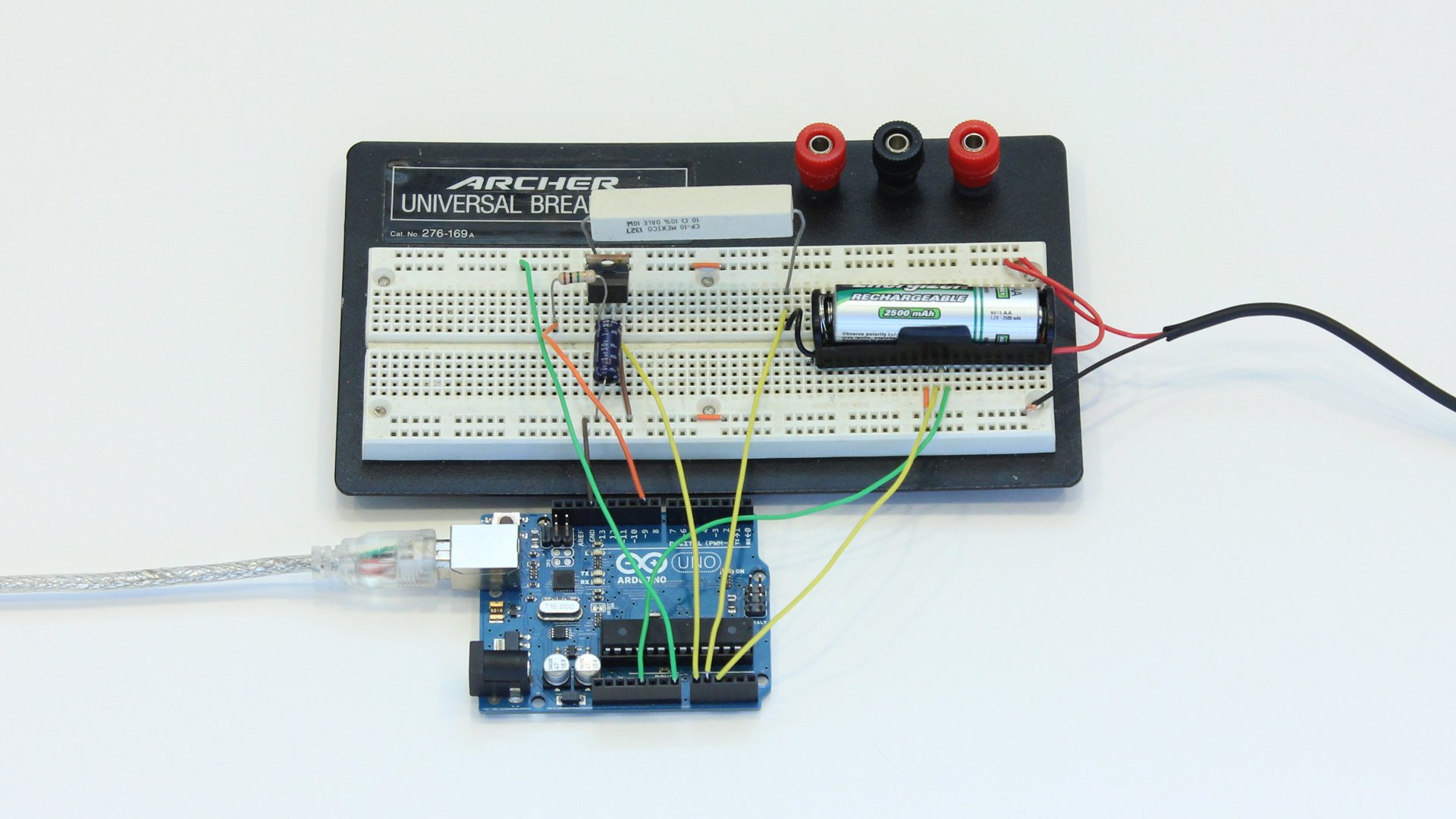
The finished device
Rechargeable batteries are a great way to power your portable electronics. They can save you a lot of money and when properly recycled, they are much better for the environment. In order to get the most out of your rechargeable batteries, they need to be properly charged. That means that you need a good charger. You could spend a lot of money on a commercial charger, but it's much more fun to build one for yourself. So here is how to build an Arduino controlled battery charger.
First it is important to point out that there is no universal charging method that is appropriate for all rechargeable batteries. Each type of battery uses a different chemical process to make it work. As a result, each type of battery needs to be charged differently. We can’t cover all the battery types and charging methods in this article. So for simplicity, we are going to focus on the most common type of AA rechargeable battery, Nickel-Metal Hydride (NiMH).
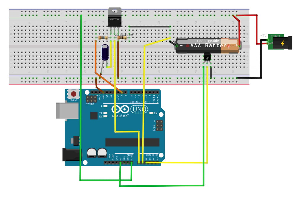
A Fritzing diagram of the project
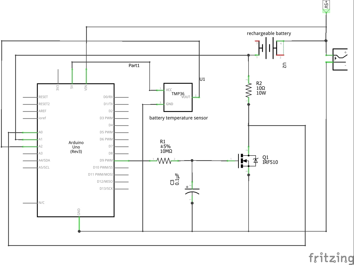
Schematic for the project
Materials:

Parts in order from left to right
- Arduino Microcontroller
- AA Battery Holder
- NiMH AA Battery
- 10 ohm Power Resistor (rated for at least 5 watts)
- 1 Mohm resistor
- 1 µF Capacitor
- IRF510 MOSFET
- TMP36 Temperature Sensor
- 5V Regulated Power Supply
- Prototyping Breadboard
- Jumper Wires
How to Charge NiMH AA Batteries

Increasing the C-rate will charge the battery faster, but will increase the risk of damaging it
There are a lot of different ways that you can charge a NiMH battery. The method that you use depends mostly on how fast you want to charge your battery. The Charge rate (or C-rate) is measured relative to the capacity of the battery. If your battery has a capacity of 2500mAh and you charge it with a current of 2500 mA, then you are charging it at a rate of 1C. If you charge it with a current of 250 mA, then you are charging it at a rate of C/10.
When charging your battery quickly (at a rate higher C/10), you need to carefully monitor the battery’s voltage and temperature to make sure that you don’t overcharge it. This can seriously damage your battery. However, when you charge your battery slowly (at a rate of C/10 or less), it is much less likely to damage our battery if you accidentally overcharge it. Because of this, slow charging methods are generally considered to be safer and will help maximize battery life. So for my DIY battery charger, I decided to use a charge rate of C/10.
The Charging Circuit
The circuit design for this charger is a basic Arduino controlled power supply. The circuit is powered by a 5-volt regulated voltage source such as an AC adapter or an ATX computer power supply. Most USB ports would not appropriate for this project because of the current limitations. The 5V source charges the battery through a 10 ohm power resistor and a power MOSFET. The MOSFET sets how much current is allowed to flow into the battery. The resistor is included as an easy way to monitor the current. This is done by connecting each terminal to analog input pins on the Arduino and measuring the voltage on each side. The MOSFET is controlled by a PWM output pin on the Arduino. The pulses of the pulse width modulation signal are smoothed out into a steady voltage signal by a 1M resistor and a 1 µF capacitor. This circuit allows the Arduino to monitor and control the current flowing into the battery.

The Temperature Sensor

The temperature sensor prevents the battery from overcharging and causing a safety hazard
As an extra precaution, I included a TMP36 temperature sensor to monitor the temperature of a battery. This sensor outputs a signal voltage that directly corresponds to the temperature. So it doesn’t require calibration or balancing like a thermistor does. The sensor is mounted in place by drilling a hole in the back of the battery housing and gluing the sensor in so that it sits against the side of the battery when installed. The pins of the sensor are then connected 5V, GND, and an analog input pin on the Arduino.

The AA battery holder before and after being placed on the breadboard

The Code

The code for this project is reasonably straight forward. There are variables at the top of the code that allow you to customize your charger by inputting the values of the battery capacity rating, and the exact resistance of your power resistor. There are also variables for the safety thresholds of the charger. The maximum allowable voltage of the battery is set to 1.6 volts. The maximum temperature of the battery is set to 35 degrees Celsius. The maximum charge time is set to 13 hours. If any of these safety thresholds is exceeded, the charger is turned off.
In the body of the code, you will observe that system constantly measures the voltages of the terminal of the power resistor. This is used to calculate both the terminal voltage of the battery and the current flowing into the battery. This current is compared to the target current which is set to C/10. If the calculated current is different from the target current by more than 10 mA, the system automatically adjusts the output to correct it.
The Arduino uses the serial monitor tool to display all the current data. If you wish to monitor the performance of your charger, you can connect the Arduino to the USB port on your computer, but this is not necessary as the Arduino is powered by the 5V power supply of the charger.

You can find a downloadable version of the full code below:
Arduino_Controlled_Battery_Charger_Code.zip
Now that you have the knowledge, you can get started on a charger of your own. Be sure to monitor your charge rate and use safety protocols, as excessively charging a battery can be dangerous.
Give this project a try for yourself! Get the BOM.


Can a recovery Rectifier like this (https://www.centralsemi.com/get_document.php?cmp=1&mergetype=pd&mergepath=pd&pdf_id=CTLHR10-06.PDF) be used in place of the MOSFET?
Now, if you could just do one for 12-V lead acids?
I have a CTEK “smart” charger tha goes through about eight stages from de-sulfurisation to maintenance charging.
I’ve often thought that that would make a nice project.
Anyhow, nicely done and probably a lot better than many of the cheapo ones.