
DIY Synth Series Part 1 — The Exponential VCO
Build a 1V octave voltage-controlled oscillator (VCO) module and create your own analogue synth sounds.
Learn how to make your own old-school 1V/octave synthesizer.
Today’s music is mostly made using computer software to master tracks, add instrumentals, mix songs, manipulate sounds and much more— but how do they use to make music?
Music used to be done entirely with REAL instruments such as guitars and pianos but synthetic sounds have made their mark on the musical scene, as well. A great band to look at for an example is Kraftwerk, which in the 1970s used synthesizers to create all their sounds from the aggressive sawtooths to the gentle beep and boop of a computer.
These synthesizers (unlike most ones you will find today) were all analogue which means that, instead of relying on software and processors, the sound generation was done by manipulating electrical signals against time.
How does an old fashion synthesizer work? This series of projects will show how all the different parts in a synthesizer work and how to build your own modules.
In this project, we will be building the heart of the synthesizer, the VCO (voltage-controlled oscillator), which takes in analogue voltages and generates the raw sounds ready to be further processed by filters, modulators, ADSR modules, and step sequences.
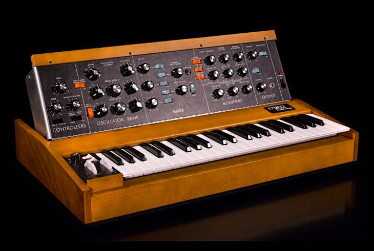
A Minimoog Model D synthesizer (the kind used by Kraftwerk from the 70s to 1981). Image courtesy of Moog.
Synthesizer Type and Music Theory
The synthesizer that we will be designing was extremely common back in the day. It's known as a 1V/Octave synthesizer. This means that for every 1V increase on the input, the output frequency will go up by one octave (i.e., by a factor of 2).
Now for this module to work correctly, it needs an exponential converter on the input. This converter will take a linear voltage in and produce an exponential voltage which is fed into the VCO. Why do we need an exponential converter? The answer is in the nature of human hearing and music theory!
If you take a piano and play the middle A note (A4), it makes a specific tone which has a frequency of 440Hz. If you now play the A note to the right of this one (12 notes up, A5) the note sounds the same except higher pitch and has a frequency of 880Hz. (The lower note is a harmonic of the upper note which is why they sound OK when played together). Now, if you play the next A note to the right (A6), the note sounds higher pitched than the previous A note; it has a frequency of 1760Hz.
Any two same notes that are separated by 12 keys is called an octave. For any two keys that are an octave apart, the upper key will have a frequency twice that of the first. The reason for this is because by nature human hearing is logarithmic. This means that for something to sound twice as loud, its amplitude (or frequency in the pitch realm) needs to go up by a factor of two.
If, for example, we increase the frequency of a waveform from 1Hz to 2Hz, that would be considered an octave apart according to the human ear. But increasing a waveform frequency from 440Hz to 441Hz does not result in an octave change. In fact, the human ear would not be able to distinguish between these two frequencies because the human ear is good at relative changes as opposed to absolute changes.
So with all that complicated theory out of the way, we need to find a method to take in a linear voltage source (1V Octave Keyboard) and convert it into a voltage source that produces exponential voltages. To do this we will use a component that has inherent exponential qualities, the bipolar junction transistor or BJT.
The Exponential Converter
So we need a circuit to take in a linear voltage from the keyboard/controllers and produce an exponential voltage which doubles in value for every octave.
Since our VCO is operating on a single supply 5V rail, the output of the converter needs to be between 0V and 5V. With a 5V input range, that gives the possibility of a 5-octave keyboard with a total of 60 keys.
The table below shows the input voltage from the keyboard and the required output voltage from the converter.
| Key | Key # | 1v Octave V | Expo Output | Frequency |
| C0 | 1 | 0.0833 | 0.1655 | 65.4078 |
| C#0 | 2 | 0.1667 | 0.1754 | 69.2971 |
| D0 | 3 | 0.2500 | 0.1858 | 73.4177 |
| D#0 | 4 | 0.3333 | 0.1969 | 77.7834 |
| E0 | 5 | 0.4167 | 0.2086 | 82.4086 |
| F0 | 6 | 0.5000 | 0.2210 | 87.3089 |
| F#0 | 7 | 0.5833 | 0.2341 | 92.5005 |
| G0 | 8 | 0.6667 | 0.2480 | 98.0009 |
| G#0 | 9 | 0.7500 | 0.2628 | 103.8284 |
| A0 | 10 | 0.8333 | 0.2784 | 110.0023 |
| A#0 | 11 | 0.9167 | 0.2950 | 116.5434 |
| B0 | 12 | 1.0000 | 0.3125 | 123.4734 |
| C1 | 13 | 1.0833 | 0.3311 | 130.8155 |
| C#1 | 14 | 1.1667 | 0.3508 | 138.5942 |
| D1 | 15 | 1.2500 | 0.3716 | 146.8355 |
| D#1 | 16 | 1.3333 | 0.3937 | 155.5668 |
| E1 | 17 | 1.4167 | 0.4171 | 164.8172 |
| F1 | 18 | 1.5000 | 0.4419 | 174.6178 |
| F#1 | 19 | 1.5833 | 0.4682 | 185.0011 |
| G1 | 20 | 1.6667 | 0.4961 | 196.0018 |
| G#1 | 21 | 1.7500 | 0.5256 | 207.6567 |
| A1 | 22 | 1.8333 | 0.5568 | 220.0046 |
| A#1 | 23 | 1.9167 | 0.5899 | 233.0868 |
| B1 | 24 | 2.0000 | 0.6250 | 246.9468 |
| C2 | 25 | 2.0833 | 0.6622 | 261.6311 |
| C#2 | 26 | 2.1667 | 0.7015 | 277.1885 |
| D2 | 27 | 2.2500 | 0.7433 | 293.6709 |
| D#2 | 28 | 2.3333 | 0.7875 | 311.1335 |
| E2 | 29 | 2.4167 | 0.8343 | 329.6345 |
| F2 | 30 | 2.5000 | 0.8839 | 349.2356 |
| F#2 | 31 | 2.5833 | 0.9364 | 370.0022 |
| G2 | 32 | 2.6667 | 0.9921 | 392.0037 |
| G#2 | 33 | 2.7500 | 1.0511 | 415.3134 |
| A2 | 34 | 2.8333 | 1.1136 | 440.0092 |
| A#2 | 35 | 2.9167 | 1.1798 | 466.1736 |
| B2 | 36 | 3.0000 | 1.2500 | 493.8937 |
| C3 | 37 | 3.0833 | 1.3243 | 523.2621 |
| C#3 | 38 | 3.1667 | 1.4031 | 554.3769 |
| D3 | 39 | 3.2500 | 1.4865 | 587.3419 |
| D#3 | 40 | 3.3333 | 1.5749 | 622.2670 |
| E3 | 41 | 3.4167 | 1.6685 | 659.2690 |
| F3 | 42 | 3.5000 | 1.7678 | 698.4711 |
| F#3 | 43 | 3.5833 | 1.8729 | 740.0044 |
| G3 | 44 | 3.6667 | 1.9843 | 784.0073 |
| G#3 | 45 | 3.7500 | 2.1022 | 830.6268 |
| A3 | 46 | 3.8333 | 2.2272 | 880.0185 |
| A#3 | 47 | 3.9167 | 2.3597 | 932.3471 |
| B3 | 48 | 4.0000 | 2.5000 | 987.7874 |
| C4 | 49 | 4.0833 | 2.6487 | 1046.5242 |
| C#4 | 50 | 4.1667 | 2.8062 | 1108.7538 |
| D4 | 51 | 4.2500 | 2.9730 | 1174.6838 |
| D#4 | 52 | 4.3333 | 3.1498 | 1244.5341 |
| E4 | 53 | 4.4167 | 3.3371 | 1318.5379 |
| F4 | 54 | 4.5000 | 3.5355 | 1396.9423 |
| F#4 | 55 | 4.5833 | 3.7458 | 1480.0088 |
| G4 | 56 | 4.6667 | 3.9685 | 1568.0147 |
| G#4 | 57 | 4.7500 | 4.2045 | 1661.2537 |
| A4 | 58 | 4.8333 | 4.4545 | 1760.0370 |
| A#4 | 59 | 4.9167 | 4.7194 | 1864.6942 |
| B4 | 60 | 5.0000 | 5.0000 | 1975.5747 |

The component that will be used for its exponential properties is the BJT. Most will be familiar with the equation that relates the base current to the collector current but this relationship is linear.
The equation that relates the base-emitter voltage to the collector current is exponential:
Where
- Ic - Collector current
- Is - Saturation current
- q - Electron charge
- Vbe - Base-emitter voltage
- k - Boltzmann Constant
- T - Temperature (in kelvin)
Luckily for us, there are clever people who have already done the hard mathematics (see here for the math) and the circuit design.
Below is the complete exponential converter that will be used in our VCO engine to convert the input linear voltage into an exponential voltage (where the voltage output doubles for every 1V increase in the input).

Click to enlarge.
In the schematic, shown above, there are three different inputs feeding into U1B. You can add additional 100K resistors for more inputs but typically three should be enough.
- KEY - This is the input from the 1V Octave Keyboard
- TUNE - This is connected to a trimmer which can be used to make small adjustments to the output frequency (by adding a small amount of voltage)
- LFO - Low-Frequency Oscillator - This can be used to add effects such as UFOs, police sirens or even arpeggios
Here is a simple explanation of how this circuit works:
- U1B is used to both sum the individual inputs (KEY, TUNE and LFO) and scale the input voltage such that 1V in produces -18mV on the output (note that it’s an inverting configuration).
- Q1 and Q2 form a differential pair.
- U2B is used to maintain constant current through Q1. Changes in Q1’s base voltage lead to corresponding changes in Q2’s base-to-emitter voltage and, consequently, exponential changes in Q2’s collector current.
- Q1 and Q2 MUST HAVE VERY SIMILAR HFE!
- U1A is a current-to-voltage converter (R1 and RV1 are chosen so that when the input voltage is 5V, the output voltage is also 5V).
The VCO
Now it’s time to actually create an oscillator that is controlled via a voltage source.
To do this, we will use a very common layout shown below:
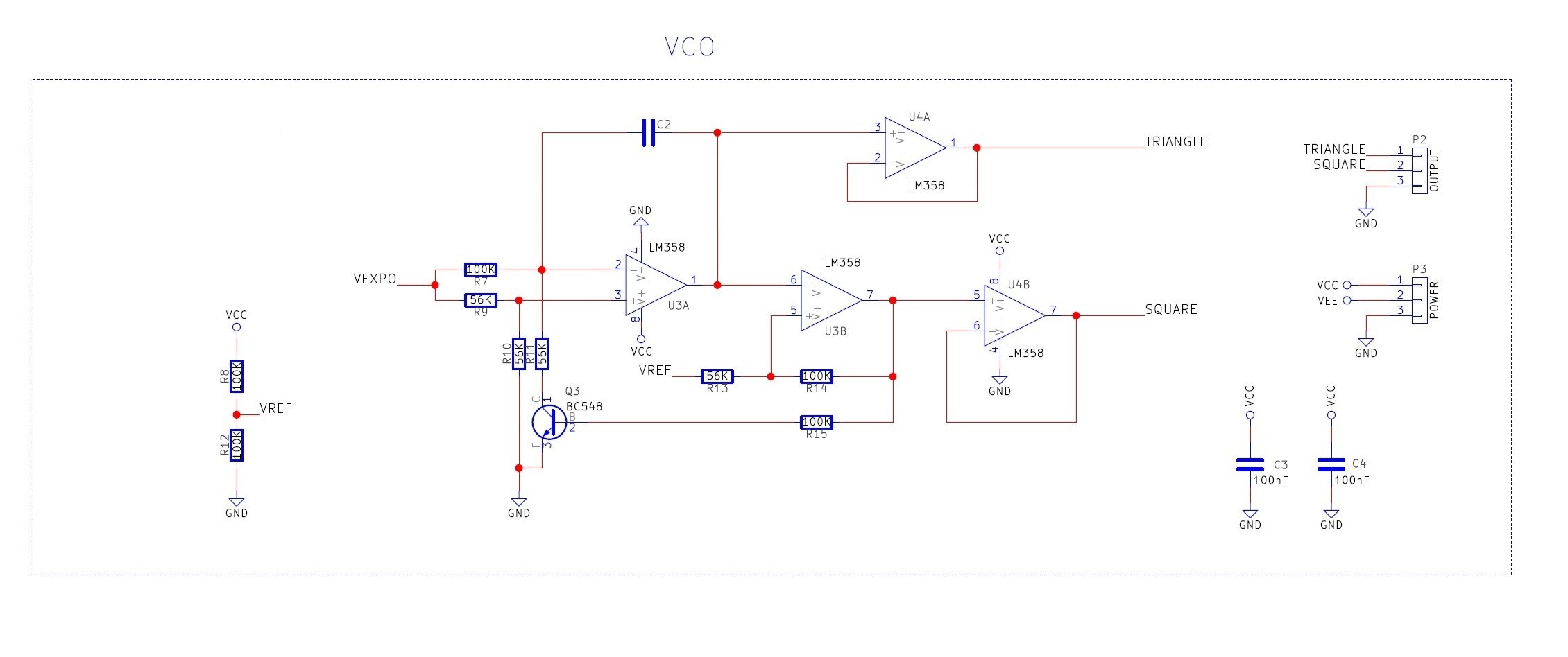
Click to enlarge.
This oscillator has four sections:
- Integrator (U3A)
- Inverting Schmitt trigger (U3B)
- Reset circuit (Q3)
- Buffers (U4A and U4B)
Integrator (U3A)
The integrator's output will do two things depending on the state of Q3 (and the presence of an input voltage at VEXPO) :
- If Q3 is off then C2 will charge and therefore the integrator output will fall gradually.
- If Q3 is on then C2 will discharge and therefore the integrator output will rise gradually.
- The rate at which the output falls or rises is determined by C2, R7, R9, R10, R11 and the input voltage VEXPO.
- The larger VEXPO is, the quicker C2 charges.
Schmitt Trigger (U3B)
The Schmitt trigger will do two things depending on the output of the integrator:
- If the integrator output crosses the upper threshold, the Schmitt trigger output will be 0V.
- If the integrator output crosses the lower threshold, the Schmitt trigger output will be 5V.
Reset Circuit (Q3)
The reset circuit Q3 will do two things depending on the output of the Schmitt trigger:
- If the trigger's output is high (5V) then Q3 will be on.
- If the trigger's output is low (0V) then Q3 will be off.
How It Oscillates
The circuit oscillates in the pattern listed below:
- Q3 is on and so the integrator's output rises.
- The integrator's output eventually crosses the Schmitt trigger's upper threshold.
- The Schmitt trigger's output now switches to 0V.
- Q3 is now off and so the integrator's output begins to fall.
- The integrator's output eventually falls below the Schmitt trigger's lower threshold.
- The Schmitt trigger's output now switches to 5V.
- Q3 now turns on (so go back to step 1).
Bill Of Materials
| Component | Quantity | Reference |
| LM358 | 4 | U1, U2, U3, U4 |
| 1M Resistor | 1 | R2 |
| 100K Resistor | 8 | R3, R4, R5, R8, R12, R14, R15 |
| 56K Resistor | 4 | R9, R10, R11, R13 |
| 22K Resistor | 1 | R1 |
| 10K Linear Potentiometer | 2 | RV1, RV2 |
| 1K Resistor | 1 | R6 |
| 1nF Capacitor | 1 | C1 |
| 4nF Capacitor (value is approximate; adjust as needed) | 1 | C2 |
| BC548 (with matched hFE) | 2 | Q1, Q2 |
| BC548 | 1 | Q3 |
| 100nF Capacitor | 6 | This is for decoupling power lines so use near each IC |
| 100K Potentiometer | 1 | Only for testing with the synth KEY input |
Construction
It is advised that you first construct the synth module on a solderless breadboard just in case the circuit does not work. Once you are confident that it functions, you can either build it onto stripboard or fabricate a PCB.
Try to construct one section and get it functioning before building the next stage. This is so that you can be sure that this portion of the circuit works!
When constructing, there are two things to keep in mind:
- Make sure that Q1 and Q2 have close hFE values (within 10 of each other). The best method is to buy a cheap bag of 100 transistors for a few dollars and use a multimeter that can measure hFE.
- Q1 and Q2 must be thermally bonded with each other. You can do this by hot gluing the two together so that the thermal change in one mirrors the thermal change in the other.

My stripboard setup.

Using the VCO
You may have noticed that the circuit has both a positive and a negative supply voltage. This circuit requires a dual power supply to function correctly (it requires 5V, 0V, and at least -5V on the negative rail). Luckily for us, this circuit works very well using the negative voltage generator project, so make sure to build that first! You can also use two batteries in series to get a split supply and use the middle connection as ground.
Here is a possible circuit that you can use to power the VCO:
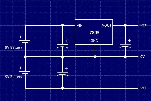
Note that only the VCC rail needs regulating to 5V because this will determine the saturation points for the VCO as well as influence the output frequency. The negative rail is used only in the exponential converter circuit, and during normal use the opamp outputs in that circuit will not be driven to the supply rails.
Testing the VCO
To test the VCO, you will need to provide input voltages to the summing stage U1B. You can either use a potentiometer to supply a variable voltage between 0V and 5V or you could use the output of an oscillator or a 1V octave keyboard if you have one. The video shown in this project uses a potentiometer connected across VCC and 0V with the varying output voltage connected to the summing stage.
In the video shown below, you will see that the VCO is connected to a potentiometer and a second VCO. The second VCO produces low-frequency oscillations (LFO) that can be used to wobble the pitch for many interesting effects. You will also notice that placing a finger on either Q1 or Q2 will result in a change of output frequency and can be exploited to make even more interesting effects! Also, note that I used a DC-blocking capacitor to remove the DC offset in the signal sent to the speaker.
Project Files
All the project files are included here and you are completely free to do as you see fit with them!
In the .zip file below, you'll find:
- Excel table of the voltages
- KiCad project files
- LTSpice simulation
- PDF version of the VCO core
Give this project a try for yourself! Get the BOM.


I built a PAIA road synth kit when I was a kid. It had two VCOs among other things.
Can someone explain to me how the exponential output column in the table was calculated?
Thanks!