
Flash Freeze Photography with an Arduino
Freeze moments in time to easily produce extraordinary close-up pictures with your digital camera, an Arduino, and these simple circuits.
Freeze moments in time to easily produce extraordinary close-up pictures with your digital camera, an Arduino, and these simple circuits.
I have always been impressed by high-speed photography. The photographic capture of what normally goes unseen, or at least unnoticed, is intriguing and oftentimes beautiful. High-speed cameras, however, are expensive and beyond the reach of many of us.
You can, however, get close to high-speed photography using a simple and inexpensive technique. In this project, we will build two simple and inexpensive circuits that, along with your DSLR camera, a slave flash, and an Arduino Uno, can reproduce some of the characteristics of high-speed photography to capture unusual moments in time.
Requirements:
- Digital camera with manual focus and ability to set long exposure times
- External (slave) flash unit (see text)
- Hot shoe with external terminal capability and a cable (see text)
- Arduino Uno
- One or both of the circuits presented here (see Bill of Materials for each below)
Basic Technique
The “secret” to this technique is simple. First, manually focus your camera. Then, set your camera exposure to a relatively long value, say 4-6 seconds, and in complete or nearly complete darkness, take a picture. Ordinarily, these conditions will produce a totally black picture. During the long exposure period, however, the flash will fire and provide the only illumination during the exposure. A brief moment captured by the flash.

The complete FSR interface circuit on a breadboard with an Arduino Uno
The key is to control the firing of the flash. In this project, we will use an Arduino Uno to fire an external flash when a specific external event is sensed. Almost any external sensor can be used as the trigger event for the flash. Here, we will use two sensors, a force-sensing resistor and a sound sensor, to detect the external event of interest.
Camera
The camera that I used for this project is a Canon EOS 400D (Digital Rebel XTi). This is a relatively low-end (and, now, relatively old) digital SLR (single lens reflex) camera. Any camera with a manual focus and the ability to set long exposures should work. As with any close-up photography, you need a lens that can focus at the desired distance.
Flash Unit

The PL-ASF18 slave flash unit
We want the Arduino to trigger the flash, so we need an external flash unit. I used a Polaroid PL-ASF18 slave flash unit, pictured above. This is one of the lowest-priced slave flash units around and it works quite well. One particular advantage is that it can be triggered with a relatively low voltage (<6 V). (Other triggering standards use higher voltages.) For the circuit that follows, it is critical that you use an external flash that accepts a low-voltage flash trigger.
The PL-ASF18 is quite strong for close-up work, yet it operates from two 1.5 V AA batteries. You will likely need to bounce the flash to the target rather than aim it directly at the target. For the shots in this article, I did not point the flash unit directly at the target; rather, the flash was pointed directly away from the target, and the light reached the target by reflecting off a piece of black cardboard. Additionally, I used a light diffuser (a white nylon sheet tent) for some shots. If you have a unit with variable flash power that can be configured externally (the PL-ASF18 does not have that capability), you may be able to accomplish the same effect by reducing the power.
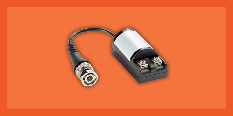
Hot Shoe

Hot shoe with 3.5 mm socket
The external flash unit connects to a hot shoe, which is a somewhat standardized “socket” for a flash unit. I used the one pictured above (available here), which contains multiple shoes. More importantly, this hot shoe has a convenient 3.5 mm socket where you usually see the common PC Sync connector. That connector externalizes the center contact and the shoe mount—when shorted, the connection will operate the flash. Most any hot shoe with the "standard" PC Sync connector (example here) will do the same. The advantage of this hot shoe, however, is that the 3.5 mm socket is very common, as is the mating jack.
Regardless of which type of connector you use, you will also need to make a cable with the two leads from the hot shoe for attaching to our circuit. You will need to identify the positive and negative leads using a voltmeter for correct connection. You will also need to measure the voltage between these contacts to make sure that the voltage used to operate the flash is within the limits of our circuit (see further explanation below). The hot shoe, with the flash unit attached, can be mounted on a mini-tripod to facilitate positioning.
Force-Sensing Resistor

Interlink 406 force-sensing resistor
The Arduino needs to monitor some external event in order to operate the flash at the desired time. The external event for this version of the project is force, which we will measure using an Interlink 406 force-sensing resistor (PDF). The force-sensing resistor (FSR) is pictured above and is available from Adafruit and other sources. You can download the integration guide linked from this page for additional information on the sensor.
The resistance between the leads of this sensor varies according to the force exerted upon its surface. That is, if you drop a small object on the surface or tap on it, the resistance will change. The Arduino will use this characteristic to sense an external event and trigger the flash.
The leads from the FSR should be attached to a cable to connect to our circuit. As mentioned in the integration guide linked above, to avoid damaging the FSR, do not directly solder to the leads. Instead, use female jumper leads, which can be crimped slightly to provide a tight fit.
Schematic for the FSR-Based System
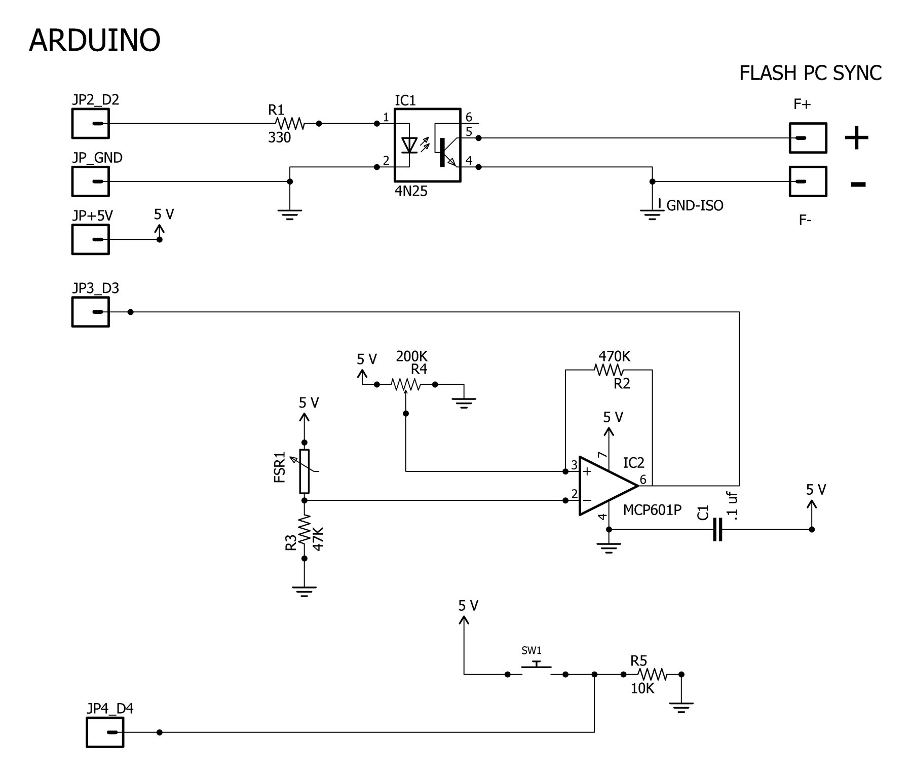
Schematic for the Arduino interface to the FSR and flash unit. Click to enlarge.
The schematic above is for the entire circuit that allows the Arduino UNO to monitor the FSR and trigger the external flash. The circuit has three distinct parts: top, middle, and bottom.
Top—External Flash Unit
The top portion allows the Arduino to control the external flash unit. A logic-high signal on pin D2 will activate the LED inside the 4N25 optoisolator. The NPN transistor in the 4N25 will then turn on.
The collector and emitter terminals of the 4N25 are connected, respectively, to the positive and negative terminals of the flash trigger (the flash-trigger connections come from the cable plugged into the hot shoe socket). Thus, when the LED is energized by the Arduino, the flash will be triggered.
Note that the flash unit is electrically isolated from the Arduino, and that is desirable. You must first measure the voltage at the terminals of the flash unit (i.e., on the leads coming from the hot shoe cable) to identify the positive and negative terminals and to make certain that you are not exceeding the maximum collector-to-emitter limits of the optoisolator. If you have the leads reversed or the voltage exceeds the specified maximum, you will likely fry the optoisolator.
For the Motorola 4N25 that I used, the maximum collector-to-emitter voltage is 30 V, but not all optoisolators marked 4N25 are the same, and you should consult the manufacturer’s datasheet to determine the limit for your component. I measured this voltage for the PL-ASF18 unit with fresh batteries and it was ~5.5 V, which is well below the maximum. But, as already mentioned, different flash units can use different trigger voltages, so measure the voltage first.
Middle—Force-Sensing Resistor and Op Amp
The middle of the schematic contains the FSR interface and uses an MCP601P op amp (PDF). It is by no means necessary to use this exact op amp; the MCP601P was chosen because it is designed for single-supply operation and features a rail-to-rail output. The MCP601P is used in a comparator configuration, such that it functions as a threshold switch.
The inverting input to the MCP601P is fed by a voltage divider formed by R3 and the FSR. R3 is 47 kΩ and was chosen to function well in the circuit over the low end of the force–resistance curve, as shown in Figure 10 of the aforementioned FSR integration guide.

Image courtesy of Interlink Electronics
The non-inverting input to the MCP601P is also fed by a voltage divider from the wiper of R4, a 200 kΩ multi-turn potentiometer. Adjusting the potentiometer changes the amount of force required to generate a trigger signal from the op amp.
The output of the MCP601P goes to an Arduino digital input port (D3). When no force is exerted on the FSR, the output of the op amp should be 5 V—read by the Arduino digital input as a logic high. When force is exerted on the FSR, its resistance will decrease, causing an increase in the output voltage of the FSR/R3 divider. Eventually the voltage at the inverting input will exceed the voltage at the non-inverting input, and this will drive the op amp's output voltage to ground. When the Arduino detects this logic-low signal on pin D3, it triggers the flash unit.
R2 is a hysteresis resistor, meaning that it helps to suppress spurious output transitions. This is not strictly required because, when a single trigger is detected, the flash unit is activated, and several seconds are required before the flash can be triggered again. It’s generally good practice, however, to include this resistor for a more controlled and predictable circuit. See this design note (PDF) for a more complete description of hysteresis in a comparator circuit. Also, note that the circuit breadboarded for this project was able to function effectively without C1, but it is good practice to include a power-supply decoupling capacitor for both analog and digital ICs.
Bottom—Input Switch
The bottom of the schematic simply contains a momentary switch connected to a digital input (D4) of the Arduino. The input will be read by the Arduino as logic low when not pressed and logic high when pressed. We will use this switch input in the software to “arm” the flash unit; after this, the program will wait for the trigger event.
| Component | Description |
| C1 | 0.1 μF capacitor |
| R1 | 330 Ω resistor |
| R2 | 470 kΩ resistor |
| R3 | 47 kΩ resistor |
| R4 | 200 kΩ multi-turn potentiometer |
| R5 | 10 kΩ resistor |
| IC1 | 4N25 optoisolator |
| IC2 | MCP601P op amp |
| FSR1 | FSR 406 force-sensing resistor |
| SW1 | momentary switch |
Software
The Arduino software used to operate the circuit, ImpactFlash.ino, is included below. It is relatively short and should be easy to understand.
Essentially, the software waits for SW1 to be pressed. When this occurs, the Arduino's onboard LED is lit, indicating the "armed" state. Then the software waits for a change from "high" to "low" on the trigger input.
When a trigger signal is received, the flash unit is operated. If you'd like, you can insert a short delay after the trigger and before the flash is operated. Sometimes your photographic objective will require a few milliseconds of delay. After flash operation, the onboard LED blinks for a programmable period of time, during which the flash unit recharges. After that interval, the code again waits for SW1 to be pressed.
You can set the variable DEBUG to 1 in order to get text output to the serial monitor at various points in the program. By default, DEBUG = 0, since the program is likely to be used in a stand-alone fashion, but the serial monitor output can help you to gain familiarity with the program or to test the program after changing some parameters.
Code
Download the program files below.
Instructions for Use

Candy mints
To further illustrate operation, here are the steps used to take the shot above, which captures a cluster of candy mints falling. When one of the mints hit the FSR (which is under the paper), the Arduino software detected the event and triggered the flash, capturing the moment.
- Set up your "studio," including connecting the flash unit and the FSR to the circuit and switching the flash unit on. Aim the flash away from the target area and, if necessary, use a diffuser (as stated earlier).
- Position the FSR under a thin piece of paper. Note exactly where the FSR is located because that is the target area for impact detection.
- Set your camera to a long exposure—4 to 6 seconds, for example.
- Manually focus your camera. If possible, first place the objects that you are going to capture near the target area, so that you can set the focus for that spot.
- Shut off all lights—the darker the better.
- Arm the circuit by pressing SW1. Note that the onboard LED on the Arduino lights up.
- Operate the camera’s shutter.
- Drop the objects on the target area.
- The flash unit operates when an object impacts the FSR. Note that the onboard LED now flashes, indicating that the flash unit needs to recharge.
- The shutter closes and the picture has been taken.
Here are some more examples.

Match sticks

Gum balls

Halloween candy sprinkles
If you get tired of dropping things, you can always start breaking stuff, but be careful.

Formerly a light bulb
Using a Sound Sensor
While the shots above were taken using the FSR as a sensor, you don’t have to limit the technique to a force trigger. Another option is to use sound as the trigger.
Many microphone amplifier circuits have been published, so you really don't need to design your own from scratch. A particularly convenient and relatively inexpensive option is a sound sensor module built specifically for interfacing to an Arduino.

Arduino sound sensor modules
Three such sound sensor modules are shown above. The first (from left to right) is from DFROBOT; it uses an LM358 op amp and has an analog output signal. The second, from SimplyTronics, uses a 555 timer and has a digital output. The third, from Keyes, uses an LM393 comparator and has both digital and analog outputs. All three modules feature a potentiometer for adjusting the sensitivity.
Here, we will use the first module to illustrate the technique.

Schematic for the Arduino interface to the sound sensor and flash unit. Click to enlarge.
The schematic above is the complete circuit for using the sound sensor as the trigger. It is identical to the FSR schematic except that the sound sensor module has replaced the FSR and op-amp circuit. The output from the sound sensor connects to an Arduino analog input pin (A0).
| Component | Description |
| R1 | 330 Ω resistor |
| R2 | 10 kΩ resistor |
| IC1 | 4N25 optoisolator |
| SW1 | momentary switch |
| Sound Sensor | DFR0034 (see text) |
More Software
The Arduino software used to operate the circuit with the sound sensor, SoundFlash.ino, is also included in the downloadable file above. Its operation is essentially identical to the ImpactFlash.ino program except that a threshold analog value is set in the program to determine when the sound is sufficient to trigger the flash unit.
When using the circuit with very low-volume sounds, such as those made by water drops, there are additional considerations. The potentiometer on the module must be adjusted for maximum sensitivity. Additionally, ambient noise must be minimal to avoid false triggers. In fact, the usage steps for the FSR circuit should be modified so that the camera’s shutter is operated before arming the circuit because the sound of the shutter mechanism can trigger the flash unit.
A directional microphone or one mounted on a parabolic dish would reduce false triggers caused by ambient noise. Failing that, the use of a simple paper cone around the on-board microphone can help (see more on this concept here).
The following photographs were taken using the sound-sensor circuit and software. They illustrate some interesting “fluid dynamics.”

Elegant simplicity

Milk splash

Alien milk

Fluid flower
Closing Thoughts
This is mostly a fun project that is relatively inexpensive to build and is designed to be suitable for intermediate electronics enthusiasts and photographers alike. The circuits and software are somewhat bare-bones, and there are certainly enhancements that could be added.
Personally, I have always been a great admirer of the illustration of the complexity and beauty of common events. The examples presented in this article only scratch the surface of what you can capture. Indulge your imagination and you may be surprised by the outcome.
Give this project a try for yourself! Get the BOM.


I would like to try this project but I am having trouble locating the MCP601P op amp. Can anyone suggest a source, or an equivalent op amp I can use instead? Thanks.
I have built similar using mic/amp board fed into a Adafruit Trinket. My project was made originally designed for daylight use (no flash), but I did make some changes along the way so now it works in daylight or darkness. Not that sound matters when it comes to daylight or darkness, its just the programming changes some and thus I have a small selector switch in the case I put everything in. In my project when on daylight mode the electronics controls shutter and can still fire the flash. In night mode the electronics will open shutter 1st and then fire the flash. In all cases manual shutter settings are used and are key to getting a good pic. Even a flash will have delay.
For daylight shooting the problem everyone will run into is exposure. You simply cannot hold the shutter open. In daylight a flash is not even used, but it can be if desired. What I found was, the electronics are very fast but there’s a delay time before shutter fires which is rather slow, msec worth. This delay is in the camera being used and varies depending of what camera you use. So even though my electronics were end-to-end magnitudes faster than the camera, I still had to account for the shutter delay.
To accommodate this shutter delay my Trinket has a sensitivity pot so that I can somewhat call for camera shutter a tad sooner than the actual event. It’s still a tad tricky and takes much trial & error on every type of sound event to get just right in a pic.
And I see some folks asking for fast silicon. Surely having no delay in the electronics is good, but standard “fast” switching will likely still be way faster than your flash or shutter. The rise time on a flash tube is rather long, etc. Silicon that is sub 20us should suffice for most consumer grade camera and flash gear. Fast lab style gear might demand ns silicon. But, when you get into taking pics of things that happen really fast you end up using high speed video, like 1mil fps and then picking out the frames you want to keep.
Anyways, my project was fun, I learned a bunch of things, mainly that electronics are fast and consumer cameras and flash gear is rather slow.