
An ATMega328-based Data Acquisition System
In this article I will show you how to use the internal EEPROM of an ATMega 328P microcontroller. I will use a USB-to-serial converter, and an LM35 temperature sensor. I will also give you some tips and tricks when designing a PCB.
In this article I will show you how to use the internal EEPROM of an ATMega 328P microcontroller. I will use a USB-to-serial converter, and an LM35 temperature sensor. I will also give you some tips and tricks when designing a PCB.
Requirements
- A computer running Arduino IDE 1.6.5
- A computer with EagleCAD installed
- A computer with FreeCAD installed, or another 3D modelling program installed
- A computer with CURA or another slicer program installed
- Parts from parts list
- AVR MKII ISP programmer
- DHT11/DHT22 or equivalent
- USB-to-serial converter and a USB cable
- A terminal program, like Putty, hyperTerm or GtkTerm
You can use an Arduino in this project, although I am going to design and make my own PCB. To program my microcontroller, I am using the above listed programmer.
Introduction
With this article, you will be able to find the dew-point of the surface with which the LM35 temperature sensor is in contact. The LM35 is a linear temperature sensor, which comes in different packages. In this article I am using the TO-92 format.
The circuit will take measures from 2 different sensors, and store them in its memory. When I connect the device to a computer, I will be able to extract the data, save it to a file, import them in LibreOffice Calc or Microsoft Excel, and make a nice humidity - temperature diagram. With that kind of data, I will be able to find the dew-point of the item in interest, which happens to be a piece of plastic with a mirror-like surface.
The microcontroller used in this article is the ATMega328P-PU. It has a 1kbyte EEPROM size. EEPROM is short for Electrically Erasable Programmable Read-Only Memory. This is a kind of non-volatile memory to store small amounts of data when power is removed. The data can be all from configuration, calibration, or in this example, humidity and temperature. The datasheet says: "The ATmega48A/PA/88A/PA/168A/PA/328/P contains 256/512/512/1Kbytes of data EEPROM memory. It is organized as a separate data space, in which single bytes can be read and written. The EEPROM has an endurance of at least 100,000 write/erase cycles." (Pg 20. paragraph 8.4) The bytes that will be stored are relative humidity and temperature. The microcontroller has a DHT11 sensor, a LM35 and a USB-to-serial adapter connected to it.
The DHT11 is a relative humidity and temperature sensor. Humidity is measured in percent and temperature in Celsius. This is another article that use the DHT11 sensor. It operates on 3.5-5.5v DC.
The LM35 is a precision Centigrade temperature sensor. The output is linear proportional to the Celsius temperature. 10.0 mV/0C scale factor. If the mV increase with 10, the degree increase with 10C. It operates on 5-30v DC.
To connect the circuit to a computer, I am using a USB-to-serial converter. I have a ready-made module, based on Silabs CD2102 chip. This module is the link between the microcontrollers USART RX/TX and the computers USB port.
Hardware
First I will make a block diagram to structure my work and to have a better understaning of what I want and how I want it.
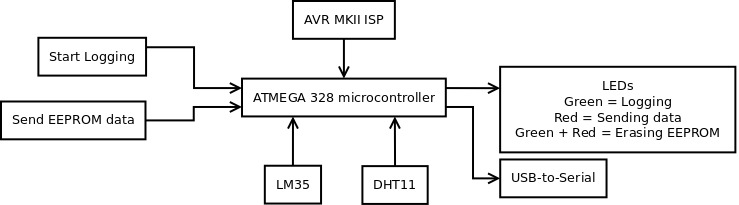
I need:
- a way to program the microcontroller -> AVR MKII ISP
- a way to start logging -> Start Logging
- a way to send the EEPROM data to the PC -> Send EEPROM data
- a way to measure temperature in Celsius -> LM35
- a way to measure humidity and air temperature -> DHT11
- a way to see what is going on -> LEDs
- a way to connect the circuit to the PC -> USB-to-serial
Schematic diagram

One habit I have when I am making a prototype is that I connect all the unused microcontroller pins to a test pad. This way, if I need to add another sensor, button or LED, I can edit the software and use the already placed pads. I do not have to make another PCB. It is very important that the hardware is built correctly and works as expected. Remember: "First comes the hardware - then comes the software." When I start a new project and a schematic, I always start with the input power. Then I consult the block diagram and add components as needed according to the blocks. As I work along, I use EagleCADs ERC. The Electrical Rule Check. This checks if pads are unconnected and that every component has a valid name and value. Use the ERC frequently; it is a great tool. Pay attention to pin 1 on JP7. My USB-to-serial converters pin 1 is 3.3v. That is why this is not connected to anything. I use 5 volts on the circuit. Do not forget to add mounting holes for the circuit.
Part list
The following image is a screenshot from Eagle.

Designing the PCB
When the schematic is designed and all the errors from ERC are taken care of, it is time to design the PCB. If the PCB has to be of a certain size, I move the outlines of the PCB in EagleCAD's Board, so the size is correct. I resize the thickness of the outline to 0.2mm. This gives a decent line to cut along when cutting the PCB. Then I place all the components inside the rectangle, and move the connectors to the edges. Here too I start with the input power and work my way through the components. When all the components are placed, I click the ratsnet button. This will rearrange the un-routed traces so they have the shortest way between the connections. If I see that if I move this component here and place that component there to shorten the traces, I do that. So, when the components are placed, and the traces are as short as they can be, I make a new rectangle following the outer edge, with the polygon tool. I name this polygon GND. When I hit the ratsnet button again, I have made a copper pour and connected it to GND. I try to have most of the traces on the bottom side of the PCB, but sometimes it cannot be done. Then I use a via and trace on the top layer, and use another via to get to the bottom side again. In this PCB, I have one wire on the top side. I have found that if I use a trace size of 0.4mm and have a 0.4mm clearance space, I can make pretty good PCBs with the toner transfer method. I think my next move is not a favorite to all, but I use the autoroute-tool. When the autoroute tool is finished, I go over each trace, and change most of the corners and elbows to 45o degrees. This can take hours, and often more than one evening. Some think of it as an art. And I must admit, a well-designed PCB is a delight for the eye.
In EagleCAD Board, there is a tool called DRC, or Design Rule Check. This tool checks for spaces and the components place. If two components are too close, for instance, you will be notified.

After I am satisfied with the PCB design, I print out the bottom layer on a glossy photopaper and iron it to the PCB. One thing that is extremely important for the result is that you clean the PCB properly. When I clean mine, I use first some fine grid sandpaper. The P500 from 3M is perfect. Then I use a drop of rubbing cream and lastly I rinse off the soap with hot water.
I etch in Ferric Chloride and I do not have the etchant near my tools. The fumes are not good for the tools.
When the PCB is etched and drilled, I check for shorts with my DMM or a web camera with an extra magnifying lens. With the DMM I use the continuous/diode setting, and put the black probe on the GND and then I probe around the signal traces with the red. If there are no shorts, I solder the jumper wires, and check them with the DMM.
The next step is to start with the input power, the capacitors and regulator. I check for shorts or solder blobs, and then I apply power. When power is applied, I measure the voltage and double check that the right volts are at the right places. If not, I take two steps back, and start checking for shorts. If all is good, I move on to the IC sockets, and the rest of the components.
When everything is soldered and looks good, I connect the programmer to the ISP-header and power up the circuit.
Software
The program is easily understood, but I am going to explain a few things. To use the DHT11 sensor, I need to import a DHT library. You can find it in the link below. Unzip it and move it to your Arduino library folder. You have to restart the Arduino IDE for the IDE to use the library. The SPI and EEPROM libraries are standard libraries that comes along with your installation.
In the setup()-function, I have the line: analogReference(EXTERNAL). This line tells the microcontroller where to find the reference voltage for the LM35 sensor. I have several options; DEFAULT, INTERNAL, EXTERNAL INTERNAL1V1 and INTERNAL2V56:
- DEFAULT, default analog reference of 5 volts or 3.3 volts on Arduino boards.
- INTERNAL, built-in reference, equal to 1.1 volts on the ATmega168 or ATmega328 and 2.56 volts on the ATmega8 (Not available on Arduino Mega)
- EXTERNAL, the voltage applied to the AREF pin. (0 to 5 volts) is used as the reference
- INTERNAL1V1 and INTERNAL2V56 are only available to the Arduino Mega board
Since the voltage applied to the AREF pin, is 5 volts regulated through capacitors and a regulator, I am using that.
To store the received bytes from the DHT11 and LM35, I am using the EEPROM.write() command. This command take two variables. The EEPROM address and the byte to be stored. The first time getDHTValues() is run, addr is set to 0 (zero). After the first EEPROM.write(), addr is increase with one: addr++; This tells the program that next time EEPROM.write() is called, it writes data in the next address place. You can think of the EEPROM as a table, with the range from 0 to 1023.
The propgram is made to read the sensors every 15. minute.
... a box to go ...
Now, when I have the PCB made, and successfully programmed it, it is time to find something to put around it. For that I use FreeCAD and a 3D printer. FreeCAD is exactly what it is; a free CAD tool. FreeCAD has a steep learning curve, but when you start to understand how it works, you can construct almost anything with it, including exporting your model to an STL.

These are the walls of the box. The top and bottom are flat squares.
Happy with my new design, I export the model as a STL file, which is imported into Cura. Cura is my favorite slicer program.

I have to do the same thing for the top and bottom parts of the box.
Now what?
The hardware is working, the software is working, and the circuit is in a nice box. Now it is time to use it. The power switch is a flip switch. The red button erases EEPROM and starts to log and store data. The green button sends the data in the EEPROM to a computer. When I hit the red button to start logging, the EEPROM is erased first, then the logging starts. If the EEPROM is full before I turn it off, the green LED is turned off. Then it is time to transfer the data to a computer. To do this you need a serial program like Putty, hyperTerm, or gtk-Term, like I am using here.
When the logger is connected to the PC, use 9600-8-N-1 as settings, and press the green button. Do not hit the red button, this will erase the EEPROM and start logging, remember? You will see some data running over your screen. This is the data stored in the EEPROM. To save this as a file, I use File -> Save RAW file. In hyperTerm it is Transfer -> Capture text. Now I have a file on my computer with the data. This file is semicolon-separated, and is easily imported to Excel or LibreOffice Calc. I save it with CSV file extension. When I open the file in LibreOffice Calc, the import wizards starts automatically.
When the data is imported, it looks like this:

You have a header; Time, Hum, Temp and Optional. The Time column is empty. Here I enter the time the logging started, and I increase with 15 minutes to the last row. If logging started at 21:00. I write 21:00 in cell A2, and 21:15 in A3, then I use my mouse to select A2:A3, and click and hold on the tiny square in the lower right corner, and drag down. Then the Time column will be filled with time in 15 minutes steps.

Using the tools in LibreOffice Calc I insert a bar-graph based on the data in the column:

With this data, I am able to find the dew point of the object connected to the LM35 temperature sensor. To see if the object is near the dew point, I use this table. First I find the right temperature in the left column. Holding a finger on that, I find the nearest humidity value. Then I move the first finger to the left, and the other down. When they meet, I have found the objects dew point. If that value is close to the value in my bar-graph or table, the object is in danger of dewing.
Download
DHT11 library, Source code, EagleCAD files and STL files for 3D printing an enclosure.
Conclusion
This has been a long article and a complete project. The main goal for this project was to make a device that logs humidity and temperature. The device then stores the data in the internal EEPROM, and make the data retrievable to a computer. With the data imported to LibreOffice Calc or Microsoft Excel, I am able to see if an object is in danger of getting covered in dew.
The LM35 wire and the power wires are only connected with solder. You have to handle the device carefully, or fasten the wires mechanically. Tie a knot on the inside of the box, with a little slack.
The next version of this device might include RTC module.
Picture and video

Give this project a try for yourself! Get the BOM.


Hello, and thank you for the project. It is unclear to me where could I download the files (source code in particular)?
Hi. It seems like there’s a link missing in the downloads section…