The Santa Cam! An Arduino PIR Motion-Activated Camera System
The motion-activated Santa Cam is sure to catch who is stealing your milk and cookies this holiday season! You can even use it for a photo booth this New Year's Eve!
The Santa Cam is sure to catch who is stealing your milk and cookies this holiday season! You can even use it for a photo booth this New Year's Eve!
BOM:
- Arduino Uno
- DSLR camera with remote shutter jack
- 2.5mm TRS cable
- Rectifier diode
- Milk and cookies

My best action shot
Why?
You see, when I was little, my dad used to set up a video camera in the corner of the living room on Christmas Eve night, right near the milk and cookies. The next morning, after obnoxiously tearing through my presents, we would sit down and scroll through the footage to see if we caught anything. Lo and behold, Saint Nick walked right past the camera—but no shot of his face!
Since my childhood, I have tried staying up time and time again to catch him, myself (he always comes right after I fall asleep)! This year, I figured I would beat the man at his own game! With just a few components and my handy-dandy DSLR, I found a great All About Circuits article and built the infamous "Santa Cam." I found my nearest spare Debra-head and strapped on the components and used her as a scarecrow (act natural, nothing to see here)!

Getting ready to make our connections
How?
First, let's understand how my camera works. Yours may be different, so double check your manual before moving forward. My Canon EOS Rebel T3i has a 2.5mm TRS (tip, ring, sleeve) remote shutter jack. A common auxiliary TRS cable, like the one you plug your phone into to play music in your car, is a 3.5mm TRS cable. I had an extra one of those lying around but the connector was too big for my camera, so I bought a 3.5mm female–to–2.5mm male adapter.
In a typical setup like mine, you can control the focus or shutter separately by shorting either of the corresponding leads to ground. On my cable, the tip (T) controls the shutter, the ring (R) controls the focus, and the sleeve (S) is ground. By shorting the tip or ring to the sleeve, we can activate one of the two functions.

How my camera shutter control functions
For our setup, we can control both the focus and the shutter if we short the tip terminal to ground long enough for the camera to auto-focus. The focus conductor is there if you'd like to control the focus separately from the shutter, i.e., if you want to focus the camera without taking a photo.
In a typical setup, with the tip shorted to ground, the camera will auto-focus and snap a picture, and then we disconnect the tip terminal from ground. Instead of using an unnecessary relay to do this, we will connect our camera directly to the Arduino while also protecting the camera from potentially harmful voltages.
Be careful here: make connections with both devices powered off and double check the circuit before powering back up. Cut the opposite end of the aux cable and strip the individual wires. Connect the cable's ground conductor to a ground pin on the Arduino so that both devices share a common reference. If you are unsure of the wire connections, check for electrical continuity with a multimeter.
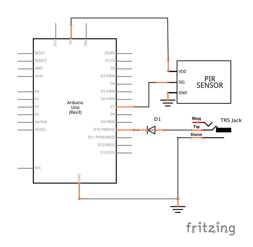
Our schematic. Click to enlarge.
The shutter terminal will be plugged into digital pin 10 but we will need to insert a diode between the shutter terminal and pin 10 to protect the circuitry inside the camera. "A diode is an electrical device allowing current to move through it in one direction with far greater ease than in the other direction," (Introduction to Diodes and Rectifiers)—basically we're preventing current flow in one direction.
We will configure the diode with the cathode pointing towards pin 10; this allows a logic-LOW signal to activate the shutter functionality, and then the Arduino's logic HIGH will not interfere with the camera's circuitry because the diode ensures that no significant amount of current will flow from the Arduino pin to the camera.

My PIR sensor
I used a basic PIR sensor, but if you prefer versatility there are other models that allow you to adjust sensitivity and range. There are three wires: one for power, another for ground, and the last for signal.
Power and ground are connected to the appropriate Arduino pin, and the signal pin is connected to digital pin 7. When motion is detected, the PIR module sends a logic HIGH signal (5 V) to the Arduino. When the Arduino detects this logic HIGH, it pulls the shutter pin LOW, keeps it LOW long enough for the camera to focus and snap a picture, and then returns it to logic HIGH.
if(val == HIGH)
  {
    digitalWrite(shutterPin, LOW);     // set the shutter pin LOW to short the terminal to ground and activate the shutter
    delay(3000);     //delay for camera to focus and take a picture
    digitalWrite(shutterPin, HIGH);     // set the shutter pin HIGH in preparation for the next photo
   }
That's it! Now you can catch the fat man in the act, or whoever is stealing all your food...
"Give this project a try for yourself! Get the BOM."
Other MIT-i Innovations:
- The Cat-Apult! (an Arduino-controlled servo for makers)
- The Launchpad-Based Laser Tripwire Alarm! (a Launchpad security system)
- The Arduino UNIVERSAL Remote Control! (an IR receiver for your entire house)
- The Crop Duster Buster! (a clap-controlled odor-management system)
- The Traffic Light Controller! (an Arduino delay statement lesson)
- The Dancing Ghostbusters Toaster! (a lesson on solenoids and inductive loads)
- The Raspberry Pi Object Detection Cat Toy! (a lesson on the RPi GPIO)
- The Zambroombi! (an object-avoidance robot)
- The Holiday Season Analog Alarm! (a gift-defending system)