
How to Use Relays to Control High-Voltage Circuits with an Arduino
To control high-voltage or high-power circuits with an Arduino, you have to isolate them from the Arduino with a relay. Here's how!
To control high-voltage or high-power circuits with an Arduino, you have to isolate them from the Arduino with a relay. Here's how!
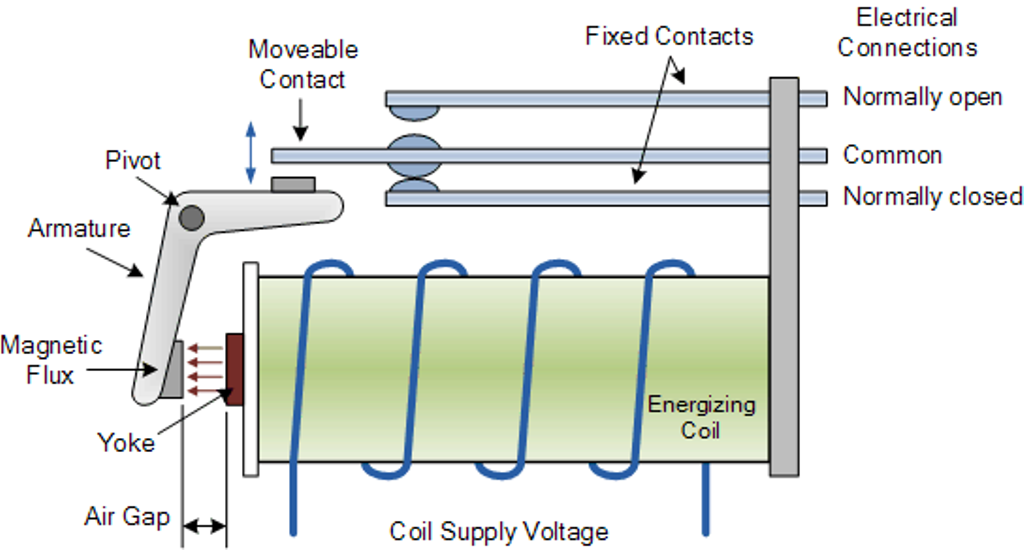
Circuits that operate at high voltages or at high currents cannot be controlled directly by an Arduino. Instead, you use a low-voltage control signal from the Arduino to control a relay, which is capable of handling and switching high-voltage or high-power circuits. A relay consists of an electromagnet that, when energized, causes a switch to close or open. Relays provide complete electrical isolation between the control circuit and the circuit being controlled.
Pins in a Typical Relay
A relay typically has five pins:
- Coil input pin1. This is generally connected to the positive terminal of your signal source.
- Coil input pin2. This is generally connected to the negative terminal of your signal source.
- Normally Open pin(NO). This pin is normally not connected to the common pin, it is connected when the relay is activated.
- Normally closed pin(NC). This pin is normally connected to common pin and is disconnected when relay is activated.
- Common. In most of the cases, this pin is connected to the ground of the source we use to drive the appliance.
Contactor
Project: Controlling High-Voltage Circuits with a Relay and an Arduino
In this tutorial, we will turn on a 12V motor using a relay. An optocoupler is added to provide even more isolation between the Arduino and the high-power load.
Hardware Required
- 1 x 12V power supply
- 1 x DC motor
- 1 x 5V relay
- 1 x Arduino Mega 2560
- 1 x 2N2222A NPN transistor
- 1 x 4N25 Optocoupler
- 1 x 1N4148 Diode
- 1 x 1k resistor
- 1 x jumper wires
Click here for complete BOM.
Wiring Diagram
The circuit shown in the diagram below uses a relay to switch 12V across a DC motor. To turn on the motor, the program writes a HIGH value to pin 3, which activates the optocoupler which in turn switches on the transistor. When the transistor turns on, current flows through the relay coil causing the relay to close, which connects 12V across the motor, making it spin.

Arduino Code
void setup() { pinMode(3,OUTPUT); } void loop() { digitalWrite(3,HIGH); // motor runs for one sec delay(1000); digitalWrite(3,LOW); // motor stops for one sec delay(1000); }Watch the Project Video
Give this project a try for yourself! Get the BOM.


Can you supply resistor values and part numbers for diode and the transistor? Also I notice an IC you make no mention of
wow very informative, Im so glad a joined this site. wtf you have an ic in there? if your gonna writing something then actually put some effort into it d-bag.
Seriously….thats the best you can do???? Soooooo here’s an obvious question a beginner may ask…....if your using the Arduino to control the relay which will control the motor, then why are you using a transistor? You make no mention of that or the reasoning behind it. Useless article with the most BASIC info on relays possible.
Oh and whats even funnier, it was posted by “Editorial Team”......It took them a WHOLE TEAM to write this article….amazing….. lololol