
How To Use Arduino’s Analog and Digital Input/Output (I/O)
The Arduino can input and output analog signals as well as digital signals.
The Arduino can input and output analog signals as well as digital signals.
An analog signal is one that can take on any number of values, unlike a digital signal which has only two values: HIGH and LOW. To measure the value of analog signals, the Arduino has a built-in analog-to-digital converter (ADC). The ADC turns the analog voltage into a digital value. The function that you use to obtain the value of an analog signal is analogRead(pin). This function converts the value of the voltage on an analog input pin and returns a digital value from 0 to 1023, relative to the reference value. The default reference voltage is 5 V (for 5 V Arduino boards) or 3.3 V (for 3.3 V Arduino boards). It has one parameter which is the pin number.
The Arduino does not have a built-in digital-to-analog converter (DAC), but it can pulse-width modulate (PWM) a digital signal to achieve some of the functions of an analog output. The function used to output a PWM signal is analogWrite(pin, value). pin is the pin number used for the PWM output. value is a number proportional to the duty cycle of the signal. When value = 0, the signal is always off. When value = 255, the signal is always on. On most Arduino boards, the PWM function is available on pins 3, 5, 6, 9, 10, and 11. The frequency of the PWM signal on most pins is approximately 490 Hz. On the Uno and similar boards, pins 5 and 6 have a frequency of approximately 980 Hz. Pins 3 and 11 on the Leonardo also run at 980 Hz.
To map an analog input value, which ranges from 0 to 1023 to a PWM output signal, which ranges from 0 - 255, you can use the map(value, fromLow, fromHigh, toLow, toHigh) function. This function has five parameters, one is the variable in which the analog value is stored, while the others are 0, 1023, 0 and 255 respectively.
Experiment 1: Controlling the Brightness of an LED
In this experiment, we will control the brightness of LED with a PWM signal on an analog output pin
Hardware Required
- 1 x LED
- 1 x resistor
- 1 x Arduino UNO R3
- 1 x breadboard
- 2 x jumper wires
Wiring Diagram
As shown in the diagram below, an LED is connected to pin 2 of the Arduino. To change the brightness of the LED, the program will vary the duty cycle of the PWM signal output of pin 2.

Code
const int pwm = 2 ; //initializing pin 2 as ‘pwm’ variable void setup() { pinMode(pwm,OUTPUT) ; //Set pin 2 as output } void loop() { analogWrite(pwm,25) ; //setting pwm to 25 delay(50) ; //delay of 50 ms analogWrite(pwm,50) ; delay(50) ; analogWrite(pwm,75) ; delay(50) ; analogWrite(pwm,100) ; delay(50) ; analogWrite(pwm,125) ; delay(50) ; analogWrite(pwm,150) ; delay(50) ; analogWrite(pwm,175) ; delay(50) ; analogWrite(pwm,200) ; delay(50) ; analogWrite(pwm,225) ; delay(50) ; analogWrite(pwm,250) ; }Experiment 2: LED Brightness Control Using a Potentiometer
In this experiment, we will control the brightness of the LED using a potentiometer. We will the analogRead() function to read a voltage and the analogWrite() function to output a PWM signal, whose duty cycle is proportional to the analog voltage.
Hardware Required
- 1 x potentiometer
- 1 x LED
- 1 x resistor
- 1 x Arduino Uno R3
- 1 x breadboard
- 6 x jumper wires
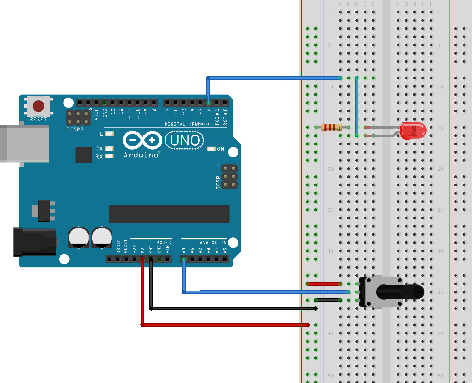
Wiring Diagram
Connect the circuit as shown below. When you rotate the potentiometer, the voltage on pin A0 will change. The program will then change the duty cycle of the PWM signal on pin 2, changing the brightness of the LED.
Code
const int pwm = 2 ; //naming pin 2 as ‘pwm’ variable const int adc = 0 ; //naming pin 0 of analog input side as ‘adc’ void setup() { pinMode(pwm,OUTPUT) ; //setting pin 2 as output } void loop() { int adc = analogRead(0) ; //reading analog voltage and storing it in an integer adc = map(adc, 0, 1023, 0, 255); /* ----------map funtion------------the above funtion scales the output of adc, which is 10 bit and gives values btw 0 to 1023, in values btw 0 to 255 form analogWrite funtion which only receives values btw this range */ analogWrite(pwm,adc) ; }Videos
Give this project a try for yourself! Get the BOM.


Super good job teaching well done!
I think you should be using pins 3, 5, 6, 9, 10, or 11 for PWM—not digital pin 2.
Also, for PWM output you shouldn’t use pinMode() on that pin. pinMode() is to specify digital inputs or outputs.
For the “teaching” ambition:
You should not create a const int adc and later on a local int adc (same name)
It is terrible and confusing when you later on do
analogWrite(pwm,adc)