
Basic Circuit Simulation with LTspice
LTSpice is a versatile, accurate, and free circuit simulator available for Windows and Mac. This is an overview of AC and DC simulation, as well as how to analyze output signals.
LTSpice is a versatile, accurate and free circuit simulator available for Windows and Mac. In this article we'll provide an overview of AC and DC simulation, as well as how to analyze output signals.
Recommended Level
Beginner (you should be familiar with analog circuit concepts to get the most out of this article)
Getting Started
To get a copy of the LTSpice executable, visit the Linear Technology design tools download page here. Once you've installed the program and run it, you'll see a screen like the one below. In order to actually begin drawing a schematic, you'll need to click the little red "LT" icon by the file menu (this creates a new draft):

From here you can start placing and editing components, but first let's go over some keyboard shortcuts. You can find most of these on the toolbar above the circuit window, or in the "Edit" and "View" menus as well, if you prefer to access them that way. If you ever get stuck working with LTSpice, there is a pretty comprehensive set of resources available in the Help menu, including more examples regarding usage. Here is a list of some hotkeys for creating your schematic:
R: Place resistor
C: Place capacitor
L: Place inductor
D: Place diode
G: Place ground
F2: Component menu
F3: Draw wire
F4: Label net
F5: Delete (press F5 then click the component)
F6: Copy
F7: Move without wires
F8: Drag/move with wires
F9: Undo (shift + F9 to redo)
CTRL+R: Rotate (when component is selected)
CTRL+E: Mirror (when component is selected)
Note that CTRL+Z does not undo; rather, CTRL+Z and CTRL+B are used for zooming in and out, respectively. Pressing space is "zoom to fit", which sizes your viewing area nicely. Now we'll start placing components and simulate a simple op-amp summing amplifier. Press F2 to access the component menu, which is where you'll find voltage sources and op-amp models. Check the screenshot below to see the pop-up component window (and the finished circuit schematic). You'll want to enter the "Opamps" subfolder and find the component called "UniversalOpamp2":
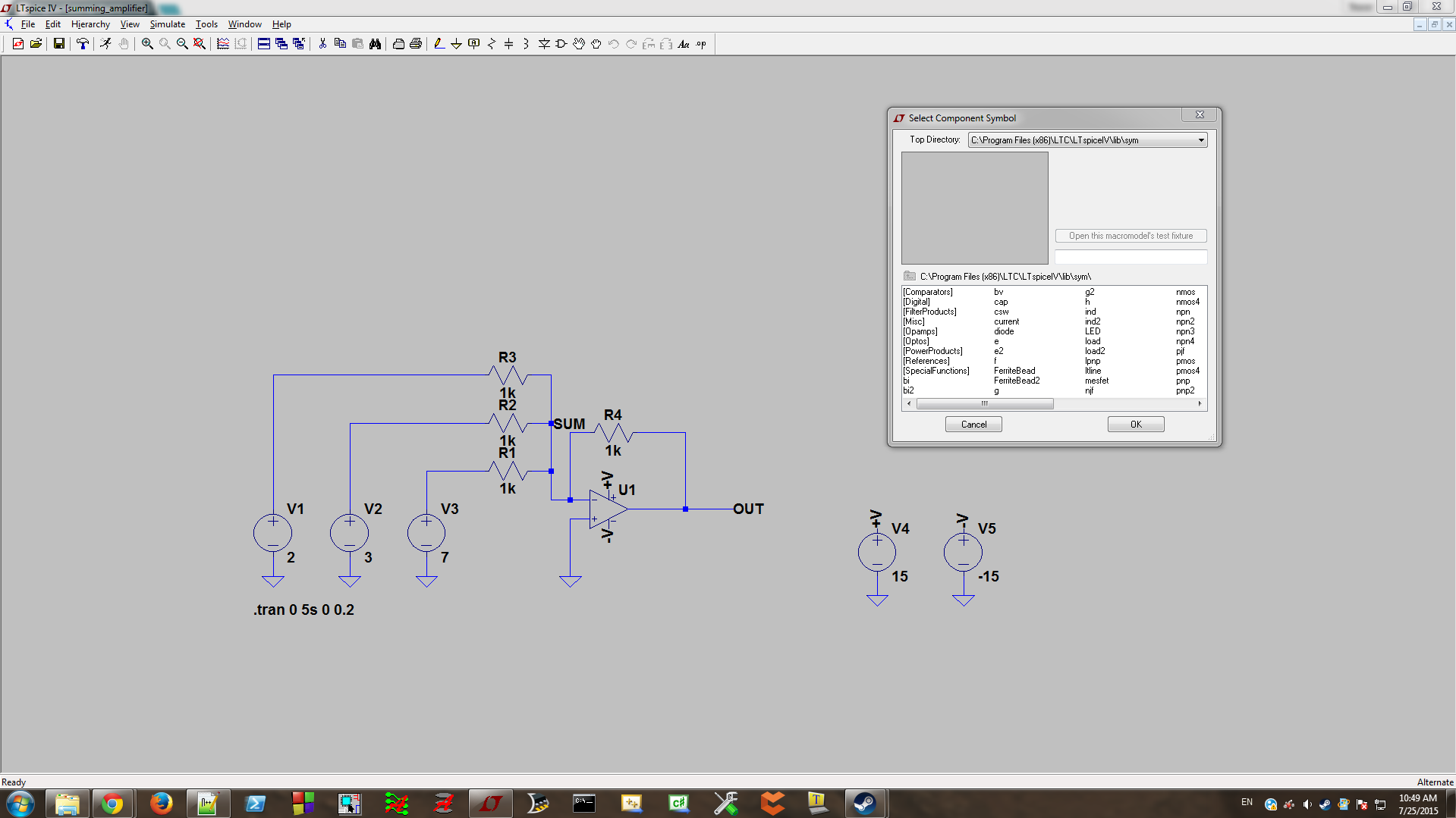
Place it anywhere on the schematic. Next you'll want to reopen the component menu and place a total of five voltage sources from the top level of the component menu (you can save time by using the copy hotkey after placing the first). Three of these should be to the left of the op-amp and two to the right. I find it's generally best to place all of your components and connect wires before editing values, so you'll also want to place three resistors in a configuration like the one shown again below. Note that your circuit should always have a ground symbol, or it will not function. If you want to rotate a component, remember to press CTRL+R while placing it:

Next you'll want to connect everything together by pressing F3 to draw wires. Once you've drawn a wire between two components, right click to end your draw. Regarding wires, clicking once will anchor the wire to the point you clicked and allow you to change direction (hold CTRL while pressing F3 to place wires that aren't at right angles), and you can draw wires directly through multiple components to connect them quickly. You'll also want to place a ground for every power supply and at the positive op-amp terminal. Something you might've noticed at this point is that the +V and -V terminals on the op-amp and on two of the voltage sources in the above schematic don't have wires connecting them. By pressing F4 (label net), you can give a particular wire or port a name. Giving the same name to two objects connects them as if you had a wire between the two and is a good way to reduce clutter (as well as specify where you are interested in probing once you actually simulate). Go ahead and use this feature to connect the terminals of your op-amp to the two right-most voltage sources.
Now it's time to give components some values. By right-clicking on any component, you can edit its properties. You'll find that the resistors will be pretty straightforward, with boxes for resistance values, tolerance and power rating. The values you enter only require letters to specify order of magnitude (so you don't have to write "ohms" after every number), and it's important to note that in LTSpice, "m" and "M" mean "milli", while you use "MEG" (or something like 1000k) to specify mega-ohms/farads/henries/etc. In the example I've given, all four resistors have a value of 1k, so enter that for each. It's a bit slower than filling out one and copying, but in the future having your circuit placed before you edit components will help ensure you don't forget things.
You shouldn't need to change anything in the op-amp's properties, but looking at them will give you a hint of some of LTSpice's more advanced features. As for the voltage sources, for this circuit you'll want to simply enter DC values. My example had input voltages of 2, 3, and 7 volts, so we should expect an inverted output of -12V when we simulate. Set the power supply voltages to +15 and -15.
One final thing before we get to simulation: you may have noticed that I used net labels to specify "SUM" and "OUTPUT". You can do this to make selecting traces easier, but remember that "SUM" should actually be around 0V.
Simulating our Summing Circuit
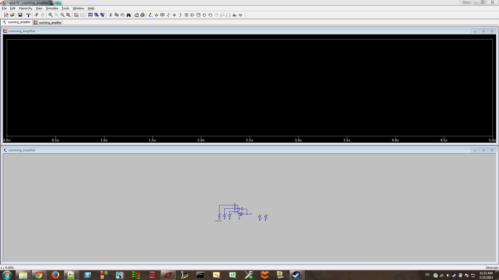
Once you've got the circuit set up like the screenshots above, you're ready to do your first simulation. LTSpice is capable of several types of simulation, but today we'll be covering just two: .tran and .AC, which stand for Transient and AC Sweep analysis, respectively. From my own experience, these are the two most commonly-used simulation forms and garner some valuable info. Open the "Simulate" menu and go to "Edit Simulation Cmd". There are several tabs here, but this time we just need to use the Transient section. Fill it out with some reasonable values (I chose a stop time of 5s and a timestep of 0.2). Hit OK and you'll now have a final component to place, which contains the simulation parameters; put it anywhere you like. After that, either right-click the schematic and hit "Run", or press it in the Simulate menu. You should see a graph fill half of the LTSpice window, but there won't be anything in it yet:
In order to get a look at the circuit output, you'll need to choose what parts of the circuit you want to see. You can do this one of two ways:
- Right-click on the black graph and hit "Add Trace", then choose the net you want to display.
- (Easier) Click on the part of the circuit you want to see a trace for. Click on a wire to see a voltage, or click on a component to get a current (which we don't need for this example).
Go ahead and click on the wires above V1, V2 and V3, and again on the "OUT" label (or the wire if you didn't add the label). This'll plot four straight lines, each in a different color. You will see that the output is -12V as expected.
AC Sweeps and Filter Simulation
Congratulations! You've simulated your first circuit in LTSpice. It was pretty basic, but you should be familiar enough with the interface now that you can continue without being too lost. A few notes about traces when simulating:
- If you ever want to plot signals relative to something other than ground, you can right-click on a node on your circuit and hit "Mark Reference". Until you set ground as the reference again, all plots you make of the circuit will be relative to that point.
- You can view differential voltages by clicking one part of circuit with your probe and dragging to the second (negative) node.
- If you want to see the current in a wire, click it while holding the ALT key. Doing this for a component will show you the part's instantaneous power.
- Removing a trace can be done by right-clicking its name at the top of the output window, or by pressing F5 and clicking it.
Now let's move on to another example. This time we're going to simulate a bandpass LC filter with a center frequency of around 50MHz. Take a look at the new circuit screenshot below:
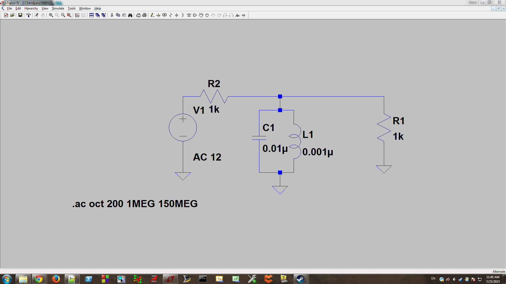
There are a couple of new things on this schematic, but we'll go through them. Go ahead and place two resistors to represent the source and load values, and put down a capacitor and inductor as shown, all using the listed values. Note that the voltage source now has a value of "AC 12"; in order to do this, when you go to set your voltage source's value, hit the "Advanced" button. Here you'll see a variety of options for signal types, but you don't need to use any of them now. Select the "None" radio button and put a value of 12 in the "AC Amplitude" box in the "Small Signal AC Analysis" section, and hit OK.
Now we're going to set up an AC sweep, that will input a range of frequencies to our filter and allow us to see the expected voltage attenuation. In order to do this, go to Simulate->Edit Simulation Cmd, and choose the "AC Analysis" tab. You should experiment with these settings to see how it affects your output - in particular, increasing or decreasing the number of points per octave will have a significant effect on the shape of your output signal. For now, choose something like what is shown below:

Once you've placed the simulation command, it's time to check out some traces. Hit "Run" and probe the voltages at the output of the voltage source and after the filter. You should see a plot that looks something like this:
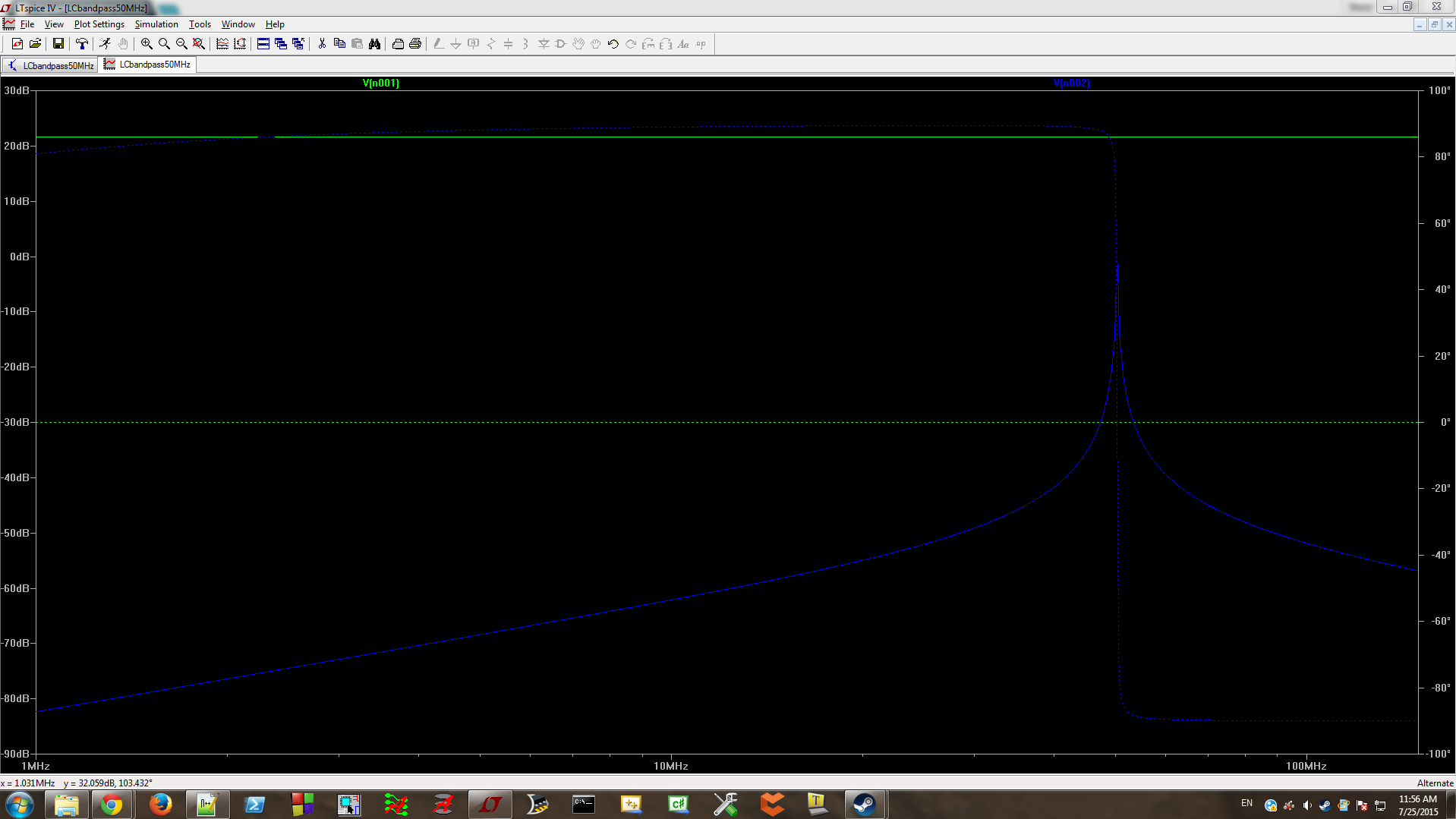
Great. Now that you've seen the simulation showing that your bandpass circuit is working, you might want to see exactly what values of attenuation and frequency the peak represents. In order to do that, you'll need to add a cursor to the plot - do this by right-clicking on the output trace's name (for me, it was the blue V(n002)) and in the pop-up, select "1st" from the "Attached Cursor" drop-down and hit OK. You can drag this across the trace to see values of attenuation, phase and delay at various frequencies. Getting an accurate assessment of the trace's peak might be difficult as-is, so you'll need to zoom in. You can zoom in by using CTRL+Z and out with CTRL+B, or you can click and drag on the black background around the peak to zoom in; then you can place the cursor more accurately. Doing this, I saw that the circuit caused an attenuation of 1.40dB at a frequency of 50.3MHz.
Closing Remarks
You should now possess enough understanding of the LTSpice interface to simulate a variety of circuits. LTSpice has far more features available than could be covered in a single article; in the next installment we'll go over some more advanced features including other waveforms, .MODEL files, varying component values, and behavioral voltage sources. Comment below if you have any questions.
Next Article in Series: Intermediate LTSpice


How to add conduction path to ground for balanced delta-delta configuration??
In theory books, delta-delta configuration don’t need a conduction path to ground.
But Ltspice is giving error:
“This circuit doesn’t have a conduction path to ground! Please flag a node as ground.”
Please help….