
Choosing and Using Ferrite Beads
This article provides practical guidance on using ferrite beads to improve your PCB’s power quality.
Use ferrite beads to improve your PCB’s power quality.
Previous Articles in This Series
- Clean Power for Every IC, Part 1: Understanding Bypass Capacitors
- Clean Power for Every IC, Part 2: Choosing and Using Your Bypass Capacitors
- Clean Power for Every IC, Part 3: Understanding Ferrite Beads
Checking Specs
The previous article discussed the importance of carefully considering impedance vs. frequency characteristics when choosing a ferrite bead: whenever possible, the targeted noise frequencies should fall within the bead’s “resistive band,” meaning the range of frequencies in which the resistive impedance dominates the reactive impedance. This is a fundamental aspect of maximizing your bead’s ability to suppress noise, but there are other specifications that you need to keep in mind—namely, DC resistance and rated current.
Unlike bypass capacitors, ferrite beads are used in series with the power line, which means that any DC current flowing through the bead will create a voltage drop proportional to the DC resistance.
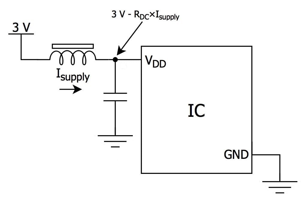
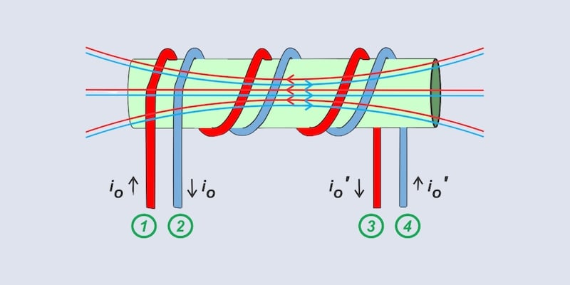
(Note: A few different circuit symbols are used to represent ferrite beads. The one shown here is not the “official” IEEE symbol, but it helps us to remain cognizant of the functional similarity between beads and inductors.)
A ferrite bead’s DC resistance—much less than an ohm for typical surface-mount parts—is rarely an issue in this age of low-power ICs. But this is precisely where you can get into trouble: if you don’t check the DC resistance spec, or if you get into the habit of throwing the same ferrite bead in front of every IC, you might not notice that an unusually high-power device could draw enough current to cause a problem. Imagine, for example, that you happen to choose a part with fairly high DC resistance, say 0.7 Ω, and that you are using one bead to filter a 1.1 V core supply connected to multiple power pins on a high-performance digital signal processor. Maybe everything is fine during normal operation, but if that processor enters a period of intense computational activity and draws 400 mA through the bead, your 1.1 V core supply just decreased to 0.82 V. This temporary, operation-dependent power supply deviation could lead to the sort of intermittent failure mode that is notoriously difficult to diagnose.
Rated current is not as straightforward as it seems. Indeed, if the steady state current through the bead is higher than the rated current, damage may occur. But there are two nuances that you need to be aware of. First, rated current is not constant over temperature:

This is the derating curve for the Wurth part discussed in the previous article. The precipitous decline beginning at 85°C should make it abundantly clear that you need to choose your ferrite beads very carefully if your system will be subjected to high temperatures. Second, DC currents well below the rated maximum can degrade the bead’s performance because the ferrite material becomes “saturated.” Ferrite saturation reduces the bead’s peak impedance and shifts the impedance curve toward higher frequencies, as shown in the following plot from Murata:

To reduce the effects of core saturation, ensure that your bead’s rated current is at least 50% (preferably 100%) higher than your expected maximum current.
Resonance: Diminished, Not Eliminated
In the previous article we discussed how ferrite beads are advantageous because they dissipate high-frequency energy and are thus less susceptible to resonance problems. However, ferrite beads are predominantly inductive over a wide range of frequencies, and they are often used in conjunction with nearby capacitors, so we cannot simply forget about resonance. Recall that an LC circuit will resonate at the following frequency:

This tells us that the resonant frequency decreases as capacitance increases. Consequently, higher amounts of capacitance near the ferrite bead increase the likelihood that the bead will be primarily inductive at the resonant frequency.
Usually you don’t have to worry much about this resonance issue—most bypass capacitors are small (namely, 0.1 µF), parasitic resistances help to dampen any ringing that may occur, and often the circuit does not generate significant noise energy at the lower frequencies that fall within the ferrite bead’s band of reactive dominance. Nevertheless, if you are using ferrite beads in conjunction with relatively large (say, above 10 µF) bypass capacitors, you may want to run a quick simulation or probe some signals to see if you notice any ringing. If you do, try to find a ferrite bead that exhibits more resistive impedance in the problematic frequency band. Alternatively, if IR voltage drops are not a concern, you can reduce the Q-factor of the resonant circuit, and thereby suppress ringing, by inserting a small series resistor near the IC’s power pin:

The “FBC” Filter
We are now ready to discuss three common ways by which your circuits can benefit from a strategically chosen ferrite bead. The first way has already been presented in the two circuit diagrams given above—a ferrite bead can be combined with a bypass capacitor to form a bead-based equivalent to the standard LC low-pass filter. This “FBC” filter theoretically approaches the two-pole response of an LC filter within the bead’s inductive frequency band, and then it transitions to the one-pole response of an RC filter as the resistive impedance begins to dominate the reactive impedance. There is a certain elegance to this: the roll-off is steeper in the lower frequencies where resonance is less of a concern, and high-frequency ringing is suppressed by the bead’s resistive properties.
At this juncture we should point out a good way to sabotage your IC, namely, using a ferrite bead without a capacitor between the power pin and ground:
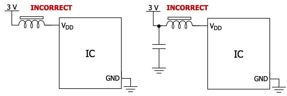
As discussed in the first article in this series, digital ICs (and to a lesser extent analog ICs) must be able to draw rapid spikes of current from the power rail. A low-ESR, low-ESL bypass capacitor adjacent to the power pin supplies this current. Now recall that an inductor (and by extension a ferrite bead) opposes changes in current. This means that a ferrite bead used in the above two incorrect configurations is blocking the transient current needed by the IC. Hence, you need a capacitor located “downstream” of the ferrite bead so that transient current can be sourced directly from the cap (i.e., without flowing through the bead).
The FBC low-pass filter is potentially beneficial for any IC that is particularly sensitive to high-frequency noise on the power line. But notice something else: the ferrite bead will also form an FBC filter with any capacitance on the other side of the bead, including the bypass capacitors attached to other ICs on the same power rail. Thus, ferrite beads help to suppress not only noise going into the IC but also noise coming out of the IC. This means that ferrite beads are particularly valuable for decoupling in PCBs with multiple digital components, because they tend to isolate each IC from noise generated by all the other ICs.
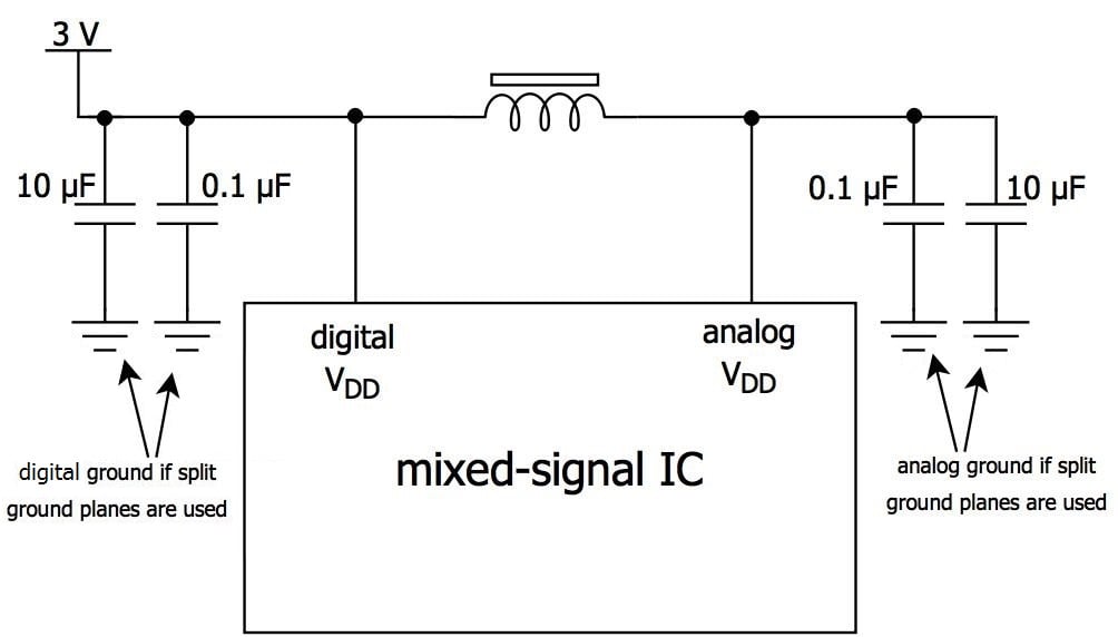
Mixed-Signal Power
It is usually preferable to supply analog and digital power to a mixed-signal IC by generating separate supply voltages via two linear regulators. But if this approach is not feasible, perhaps owing to board space constraints, you can use a ferrite bead to provide some noise isolation, as follows:
Suppressing Noise at the Source
Another time to consider ferrite beads is when you would rather use one filter at the power supply instead of individual filters attached to multiple ICs. This is an effective approach for a circuit in which a noisy DC/DC converter provides power for several analog components, which are sensitive to noise but usually do not generate large amounts of noise. A standard configuration for such a filter is a ferrite bead with a capacitor on either side; ideally the datasheet for the DC/DC converter would provide guidance on component values and other details. For example, Linear Technology recommends the following for the LTC1551, which is an inverting charge-pump regulator:

The datasheet claims that with this simple filter the output noise can be as low as 1 mV peak-to-peak.
Even though ferrite beads will be primarily inductive at the relatively low frequencies used by charge pumps and switching regulators, the resistive impedance will help to reduce ringing associated with higher-frequency harmonics.
Recap
Ferrite beads provide additional filtering and isolation that can be valuable in noisy digital environments or when highly noise-sensitive analog components must be protected. Whenever possible, choose a bead that is primarily resistive at the dominant noise frequencies, and remember to check the bead’s DC resistance and rated current so as to avoid problems related to voltage drop and core saturation.


Really nice articles you wrote there. There is one thing though, or maybe I got it wrong, but in your frequency to impedance graph by Murata you say the impedance is reduced für currents BELOW max rated current, but the graph and also the original Murata text show rather the opposite?
quote: “but the graph and also the original Murata text show rather the opposite?”
Obviously it was a ‘typo’. Common sense will tell you that saturation occurs when power gets too high. In this case, current getting too high. The graph shows reduction in impedance with increasing current. So obviously the sentence was meant to be ‘for currents ABOVE max rated current’.