
Hazards in Combinational Logic Circuits
This article covers undesired switching events, known as hazards, that can occur when developing combinational logic circuits.
This article is the second part of an introductory series on combinational circuit design and simulation using logic gates. In the previous article, we introduced the concept of combinational logic circuits and how to simplify them.
Here, we'll explore static 0-hazards, static 1-hazards, and dynamic hazards.
What Is a Logic Hazard?
In complex logic circuits, undesired and temporary switching events may occur at outputs. Figure 1 illustrates three types of hazards that can occur in combinational logic circuits:
- Static 0-hazard: The output temporarily changes to 1 when it should have stayed a 0
- Static 1-hazard: The output temporarily changes to 0 when it should have stayed a 1
- Dynamic hazard: The output changes multiple times when it should have made a single logic transition; either from 0 to 1 or 1 to 0

Figure 1. Three types of combinational logic hazards
Let’s examine the simple circuit of Figure 2 to see how a static 0-hazard is generated.

Figure 2. A combinational logic circuit with static 0-hazard
We will assume that all gates have the same propagation delay time constant d. In the timing diagram of Figure 3, inputs a = b = 0. One gate delay after input c changes from a logic 0 to 1, outputs c’ and x also change state. Since both x and y are now (temporarily) set to 1, this causes a subsequent change on the final output f from 0 to 1.
However, as the output f is changing state, so is its input y, from 1 to 0. After this change in y propagates through the final gate, the output f is returned to its final state of zero.
This is an example of a static-0 hazard:
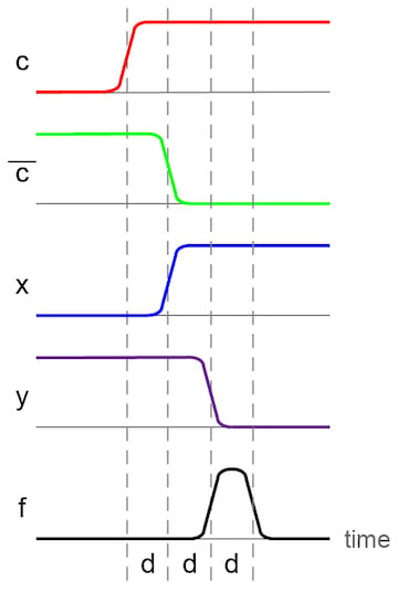
Figure 3. A timing diagram showing static 0-hazard
If we review the Karnaugh map for our circuit of Figure 2, we can see the opportunity for a static-0 hazard. There are two adjacent, but non-intersecting minterms for the 0 outputs, highlighted by the blue and tan shading. For a product of sums logic function, any two adjacent zeros that are not covered by a shared minterm can result in a static-0 hazard.

Figure 4. A Karnaugh map demonstrating static-0 hazard
The logic function derived from this using a product of sums derivation is:
$$f = (b + c)(a + \overline{c})$$
When a and b are both 0, input c can change between the 0 and 1 states without changing the “final” value for f. However, due to the differing propagation delays for certain circuit implementations, there is the potential for a static-0 hazard.
Fixing Static Hazards in Combinational Logic Circuits
We can eliminate the static-0 hazard in the circuit of Figure 2 by adding an additional grouping around the two adjacent terms as illustrated by the red highlighted box in Figure 5.

Figure 5. A Karnaugh map grouping to eliminate the static-0 hazard
The new logic function is:
$$f = (b + c)(a + \overline{c})(\overline{a} + \overline{b})$$
From a pure digital logic perspective, the third sum term in the series is unnecessary. However, this additional sum, $$(\overline{a} + \overline{b})$$, remains 0 when both a and b are 0. Thus, it is not affected by the change in c that previously caused the static-0 hazard.
Using this redundant logic, we can create a new circuit that performs the same logic function, but without the static-0 hazard. This new circuit is shown in Figure 6.
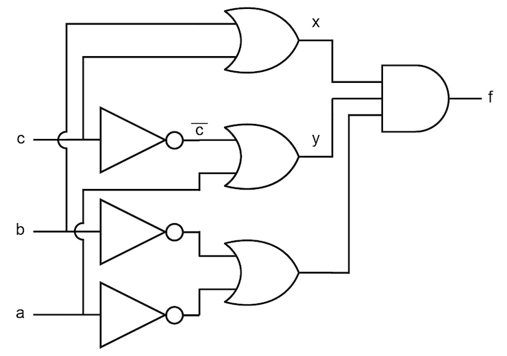
Figure 6. A combinational logic circuit that eliminates the static 0-hazard
Finding and Eliminating Static-1 Hazards
Identifying and fixing static-1 hazards is essentially the same as for static-0 hazards. Use the Karnaugh map to find adjacent logic 1 outputs that are not covered by the same minterm. For every adjacent combination of 1s found, add an additional grouping to eliminate the potential hazard.
Asynchronous Versus Synchronous Logic
The transient pulse issues associated with hazards are rarely a problem in synchronous circuits. They are designed to allow sufficient time in each clock period for the glitches of both static and dynamic hazards to resolve.
On the other hand, asynchronous logic circuits that can respond instantly to signal changes can be greatly affected. For example, an asynchronous logic circuit that is waiting to respond to a positive 0 to 1 logic transition would erroneously react in our timing diagram of Figure 3. Even in primarily synchronous designs, the system reset and present signals are often asynchronous and, therefore, can be susceptible to hazards.
In this two-part introductory series, we have looked at some of the actual limitations of gate-level circuits for implementing logic functions. The first article introduced the concepts of design with limited fan-in gates and propagation delays. and hazards. To learn more, check out our textbook section on digital circuits.


The images in this section are taken from Roth/Kinney (“Fundamentals of Logic Design”, ISBN-13 : 978-1133628477 ) without attribution. Please credit your source, or you are plagiarizing.