Linear Amplitude Modulation Applications
In this article, we'll delve into amplitude modulation and what it's used for. Also, we will differentiate between communication methods that do and do not use modulation.
We delved into amplitude modulation and what it's used for. Also, we'll differentiate between communication methods that do and do not use modulation.
A communication that does not use amplitude modulation is baseband communication. Baseband is a signal that has a narrow frequency range and requires no modulation, i.e. without any shift in the range of frequencies of the signal. On the other hand, a communication that does use modulation is a carrier communication. Carrier communications, or carrier, for short, uses modulation to shift the waveform signal (usually sinusoidal) through its amplitude or frequency. Generally, the carrier wave has a higher frequency than the input signal.
Baseband and Carrier Communication
When talking about amplitude modulation, the term baseband is used to define a band of frequencies of a signal delivered by the source or transducer. In telephone communications, this same baseband is known as the audio band, or band of voice signals. Moving to televisions, the baseband is a video band that occupies space from the 0 to 4.3 MHz range.
As mentioned earlier, baseband signals can be transmitted without being modulated, that is, without a shift if the range of frequencies of the signal of any sort. In baseband communications, the signals have sizeable power at low frequencies, which means that they cannot be transmitted over a radio but are better suited to be transmitted over a pair of wires, coaxial or optical fibers. Two examples are telephone communications that use short-haul pulse-code-modulation (PCM) between two exchanges, and optical fibers that use long-distance PCM. Using modulation is very beneficial in utilizing the broad spectrum of frequencies available. By modulating numerous baseband signals and shifting their spectra to separate non-overlapping bands, one can use all of the available bandwidth through frequency division multiplexing (FDM). Sending signals over a long distance also requires modulation in order to shift the signal spectrum to higher frequencies in order to ensure an efficient power radiation using antennas of a rather large size.
Switching to communications that do use modulation to shift a signal’s frequency spectrum is known as carrier communication. In carrier communications, parameters (amplitude, frequency, or phase) of a certain sinusoidal carrier signal, of high frequency, is altered proportionately to the baseband signal, m(t). From modulation the signal carrier we are provided with amplitude modulation (AM), frequency modulation (FM), or phase modulation (PM). Frequency and phase modulation are actually quite similar and are classified under the category of angle modulation. This type of modulation is used to transmit analog as well as digital baseband signals. Below is an illustration of the three different types of signals after being modulated.
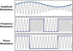
Figure 1.1 Modulation Representation. Diagram courtesy of National Instruments
Analog Modulation Techniques: Double Sideband
Amplitude modulation can be distinguished by knowing that the amplitude, A, of the carier $$A\cos(\omega_{c}t + \theta_{c})$$ varies in proportion to the message signal (baseband) m(t), or the modulating signal. Both the frequency and the phase have constant value, and we can assume that $$\theta_{c} = 0$$. By making the carrier amplitude, A, directly proportional to the modulating signal m(t), the modulated signal is represented now by$$m(t)\cos(\omega_{c}t)$$ as illustrated in Figure 1.2. This specific type of modulation will only shift the spectrum of m(t) to the carrier frequency (Fig 1.2 a).
Hence, if
$$m(t)\Leftrightarrow M(\omega)$$
then
$$m(t=\cos(\omega_{t}t)) \Leftrightarrow \frac{1}{2}[M(\omega + \omega_{c})+ M(\omega - \omega_{c})]$$ (1.2)
Knowing that $$M(\omega - \omega_{c})$$ is $$M(\omega)$$ shifted to the right by a phase of $$\omega_{c}$$ and that $$M(\omega + \omega_{c})$$ is $$M(\omega)$$ shifted to the left by a phase of $$\omega_{c}$$ will provide for a better understanding of this modulation. Having stated that, the procedure of modulation will shift the signal to the left and right by $$\omega_{c}$$. If we denote the bandwidth of the m(t) to be B Hz, then, from Fig. 1.2 c, the bandwidth of the modulated signal must be 2B Hz. Another observation is that if the modulated signal's spectrum is centered at $$\omega_{c}$$, it will have two parts: one that lies about the frequency, $$\omega_{c}$$, also known as the upper sideband (USB), and a portion that lies below the frequency $$\omega_{c}$$, also known as the lower sideband (LSB). Likewise, the spectrum centered at $$-\omega_{c}$$ has an USB and LSB too. This modulated signal does not contain a distinct component of the carrier frequency $$\omega_{c}$$. Due to this, this type of analog modulation technique is denoted as double-sideband suppressed carrier (DSB-SC) modulation.
.jpg)
FIG 1.2 DSB-SC Demodulation and Modulation
In Fig. 1.2 c, $$\omega_{c}$$ \geq 2piB if it wants to avoid an overlap of the spectra that is centered at $$\omega_{c} and $$-\omega_{c}$$. However, if $$\omega_{c} < 2piB$$, then the spectra overlap and the information held in m(t) is lost in the modulation process, which in turn makes it impossible to reacquire m(t) from the modulated signal $$m(t)\cos(\omega_{c}t)$$.
DSB-SC Demodulation
If the original signal m(t) wants to be recovered from the modulated signal, it is absolutely necessary to retranslate the spectrum over its original position. This process of recovering the signal from the original modulated signal is known as demodulation, or detection. Looking at Fig. 1.2 c, one can see that the modulated signal spectrum is shifted to the left and right by $$\omega_{c}$$ (also multiplied by one-half), the spectrum in Fig 1.2 d is obtained. This spectrum contains the desired baseband spectrum plus an additional spectrum at $$\pm 2\omega_{c}$$, however this is an unwanted spectrum. This spectrum can easily be suppressed by a low pass filter. This process is most similar and almost identical to modulation, consisting of multiplication of the incoming modulated signal $$m(t)\cos(\omega_{c}t)$$ by a carrier of $$\cos(\omega_{c}t)$$ that is followed by a low pass filter, as illustrated in Fig 1.2 e. This conclusion can be verified in the time domain by observing that the signal e(t) in Fig 1.2 e is:
$$e(t)= m(t)\cos^2(\omega_{c}t)$$
$$=\frac{1}{2}[m(t)+m(t)\cos(2\omega_{c}t)]$$ (1.2 a)
Thus, the Fourier transform of the signal e(t) can be denoted as
$$E(\omega)=\frac{1}{2}M(\omega)+\frac{1}{4}[M(\omega + 2\omega_{c})+ M(\omega - 2\omega_{c})]$$ (1.2 b)
The above equations show that the signal, e(t), consists of two parts: $$\frac{1}{2}m(t)$$ and $$\frac{1}{2}m(t)\cos(2\omega_{c}t)$$ with their spectra shown in Fig 1.2 d. This second component's spectrum, being that it is a modulated signal with frequency $$2\omega_{c}$$, is centered at $$\pm 2\omega_{c}$$. This is why this component is suppressed by the low pass filter. The final desired component $$\frac{1}{2}M(\omega)$$, is a low pass spectrum that is centered at $$\omega = 0$$, which means that it will pass through the filter unharmed. This results in the output $$\frac{1}{2}m(t)$$. The inconvenient fraction of 1/2 can be removed in the output by using a carrier of $$2\cos(\omega_{c}t)$$.
There is a possible form of low pass filter characteristics that are denoted as dotted lines in Fig 1.2 d. This method described of recovering the baseband signal is called synchronous detection, or coherent detection, where the same frequency and phase as the carrier is used for modulating the signals. Hence, for demodulation, a local carrier at the receiver in frequency and phase coherence with the carrier used at the modulator needs to be generated first.