
Power Factor, THD, and Why Linear Power Supplies Fail to Meet Power Standards
A discussion of international electrical quality standards and why basic linear power supplies fail to meet them.
International specifications set standards for the power quality of electrical and electronic equipment connected to the grid. Basic linear power supplies are unable to meet the power factor and THD specs of these standards. This article shows why.
Power factor and total harmonic distortion (THD) are key measures of the power quality of electrical and electronic equipment. In general, power factor should be as close to one as possible and total harmonic distortion should be as low as possible.
Various standards define what the levels should be for a "good" system. Linear power supplies typically cause a system to have poor power quality, and this article describes why that is and indicates what can be done about it.
International standards such as the IEC 61000-3-2 and Energy Star 80 Plus program set specifications for the power quality of electrical and electronic equipment that is connected to the electrical grid. Specifically, IEC 61000-3-2:2014 sets limits on the harmonic currents of various classes of equipment based on their maximum power levels. The Energy Star 80 Plus program specifies the minimum power factor (0.9 at 100% load) and minimum efficiency (80%) of power supplies for computer equipment.
The power quality specifications are fairly strict and the result is that the basic linear power supply can no longer be used in many applications because it is impossible for that kind of power supply to meet these international standards.
Power Quality Characteristics
Before discussing why linear power supplies cannot meet these standards, let's look briefly at the characteristics involved in these standards.
Energy Efficiency
Energy efficiency is the easiest characteristic to understand. It is simply the useful energy available to or produced by a system divided by the total energy consumed by a system. The importance of energy efficiency standards is obvious – lower efficiency means more wasted energy.
THD (Total Harmonic Distortion)
The concept of total harmonic distortion is a little bit more complicated than that of energy efficiency. THD is discussed in more detail here, but the brief description is that it is determined by summing all of the harmonic components of a signal (in this case, current) and comparing this sum to the fundamental frequency.
In other words, THD is created by all of the frequencies in a signal that are multiples of the fundamental frequency but are not the fundamental frequency.
A really general way to think about THD is as follows: a perfect sine wave has no harmonic components, and the less that a periodic signal looks like a perfect sine wave, the more harmonic components it will have. THD standards for current are important because those higher-frequency current components have various undesirable effects on electrical systems, including increased total currents, increased core losses in motors, and electromagnetic interference with other electronic equipment.
PF (Power Factor)
Power factor is also a more advanced topic than energy efficiency, and you can read a lot more details about it here. The basic idea is that power factor is the amount of real power delivered to a system divided by the amount of apparent power delivered to a system (maximum power factor is 1 and the closer to 1 the better):
$$PF=\frac{P}{\left | S \right |}$$
where PF is the power factor, P is the real power, and S is the apparent power. |S| is equal to IRMS × VRMS, and PF indicates the fraction of that apparent power that actually gets used by the system.
The remainder of the power is called reactive power, which oscillates back and forth in the system from source to load without getting used up. If two systems require the same amount of real power, the current delivered to the system with more reactive power must be higher than the current delivered to the system with less reactive power. In other words, power factor standards are important because a low-power-factor system will require a higher peak current to deliver the same amount of real power.
The two key aspects of the system that affect the power factor are the harmonic distortion (this is called the distortion factor) and the phase relationship between the AC voltage and current (the cosine of this phase difference is called the displacement factor). The more sinusoidal the current is, the closer to unity the distortion factor will be. The smaller the phase difference between the voltage and current is, the closer to unity the displacement factor will be. Combining the distortion factor and the displacement factor gives another equation for power factor:
$$PF=(distortion factor)(displacement factor)=\frac{I_{1,RMS}}{I_{RMS}}\times cos(\varphi )$$
where $$I_{1,RMS}$$ is the RMS value of the current at the fundamental frequency, $$I_{RMS}$$ is the RMS value of the total current, and $$\varphi$$ is the phase difference between the voltage and current.
Challenges in Meeting Specifications
Let's go back to why linear power supplies typically cannot meet the power quality standards of specifications like IEC 61000-3-2:2014. First, let’s examine the operation of one of these supplies and look closely at the current draw and the relationship between voltage and current.
Here is a diagram and schematic of a basic linear power supply:
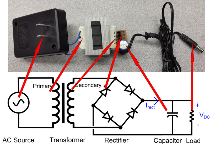
Figure 1. Linear power supply schematic and picture
It consists of a transformer to step down the grid voltage, a rectifier to convert the AC voltage of the grid to a DC voltage, a capacitor to filter the voltage, and potentially a regulator to keep the voltage at a constant value (the circuit in Figure 1 does not include a regulator).
Even if we assume that the load is linear (which it quite likely is not), the current flowing into this system from the AC side is in bursts. These bursts are primarily due to the charging and discharging of the capacitor as it filters the voltage ripple. The result of these bursts is low power factor and high harmonic currents in the system.
Figure 2 shows the current into the DC side of the system (Irect) in relationship to the voltage to the load (VDC). Note the large spikes of current followed by periods of no current – despite the fact that current to the load itself is more or less constant, the AC side of the power supply must deliver current in bursts.
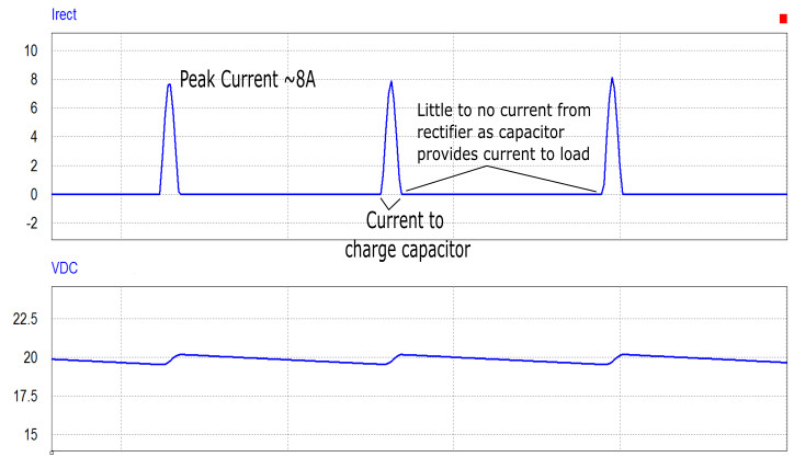
Figure 2. Current from rectifier and DC voltage across load
The current on the AC side due to the large spikes on the DC side can be seen in Figure 3, which shows the AC current in relationship to the AC voltage. The AC voltage is sinusoidal, but the AC current is not.
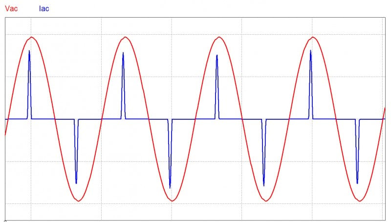
Figure 3. AC voltage and current of linear power supply
The periodic but non-sinusoidal nature of the AC current gives an indication that the power factor will be low and the THD will be high. Power quality measurements on this system show that the power factor is around 0.35 and the total harmonic distortion is more than 30%. These values are not anywhere close to meeting the specifications of either IEC 61000-3-2 or Energy Star 80 Plus.
Smoothing Current with an Inductor
To reduce the current harmonics and increase the power factor, the current must be made smoother, such that it more closely matches the shape of the AC voltage. That is, we'll need to make the current sinusoidal and in phase with the AC voltage.
A simple way to make the current smoother is to add an inductor at the output of the rectifier. This inductor will act as a filter that can smooth out sharp changes in current. A power supply circuit with an added inductor filter is shown in Figure 4.
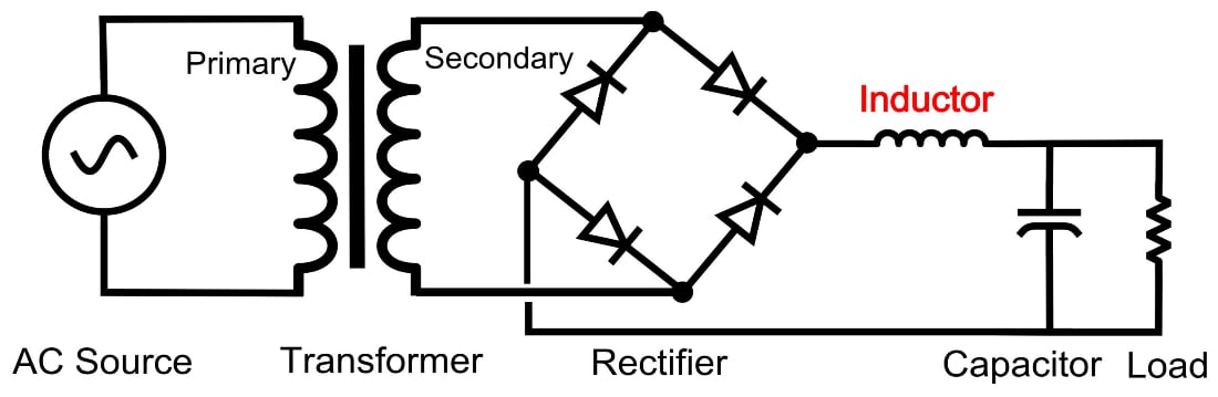
Figure 4. Linear power supply with inductor filter
The inductor current on the DC side for this new circuit is shown in Figure 5. The current is still delivered in bursts, but now the peak current is lower and the bursts are much less abrupt. This means that the AC side will not have to provide such large, intense spikes of current. This partial smoothing of the current helps to improve the power quality of the system.
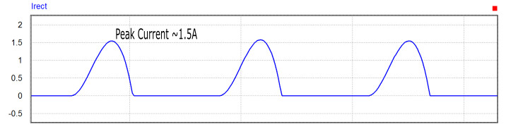
Figure 5. Current from rectifier when inductor filter is used
Measurements of the current and voltage on the AC side are shown in Figure 6; these waveforms give more evidence that the power quality is improving. The current is still out of phase with the voltage, but it's looking more sinusoidal.
.jpg)
Figure 6. AC voltage and current with filter inductor
Measurements of both the power factor and THD do indeed show significant improvement: the power factor is around 0.7 and the THD is around 20%.
However, these improvements are still not enough to meet the power factor or THD requirements of IEC 61000-3-2 or Energy Star 80 Plus. Something more radical than a passive current filter will need to be added to the circuit to meet those specs.
The type of circuit that will be able to meet the PF and THD specifications will be something that forces the AC current to follow the AC voltage, thus causing the power factor to be very close to one and keeping the THD very close to zero. This circuit will require sensors to monitor the voltage and current, as well as a feedback system to force the current to follow the voltage.
A switching circuit of some kind will be required, and one of the most common types of circuits that can implement this improvement is called a "boost power factor correction" (or "boost PFC") circuit. As the name suggests, this circuit is based on a boost converter and can significantly improve the PF and THD.
Conclusion
This article introduces the idea of power quality requirements for electrical and electronic systems, and it shows that a standard linear power supply (even when a filter inductor is added) is unable to meet basic power quality requirements.
Ensuring that a power supply will meet power quality requirements such as those in IEC 61000-3-2:2014 requires adding a system that will control the AC current to ensure that it matches the sinusoidal AC voltage as closely as possible. This can be accomplished with a boost power factor correction circuit, and a description of how this switching circuit works will be provided in a future article.


Boost PFC is one approach. There are several others for Passive PFC. Especially in < 100W circuits. For example: Valley Fill Circuit
https://en.wikipedia.org/wiki/Valley-fill_circuit
Improved Valley Fill Circuit:
https://www.coilws.com/Publications/ImprVF.pdf
AC Side Passive PFC
http://www.nuvation.com/blog/electronic-design-services/power-supply-basics-passive-power-factor-correction
More than you ever want to know:
http://www.onsemi.com/pub_link/Collateral/HBD853-D.PDF