
T Is for Toggle: Understanding the T Flip-Flop
This tech brief provides an overview of a somewhat uncommon member of the flip-flop family.
This tech brief provides an overview of a somewhat uncommon member of the flip-flop family.
Related Information
Flip-flops are fundamental components in the world of digital electronics. These devices are used as clock dividers and one-bit storage elements, and by connecting multiple flip-flops in the right way you can make shift registers, storage registers, and counters. Unlike mere logic gates, flip-flops utilize feedback to create circuits (called sequential logic, as opposed to combinational logic) in which the future state is influenced by the previous state.
If you want to make a flip-flop, you start with a gated latch, such as the gated SR latch:
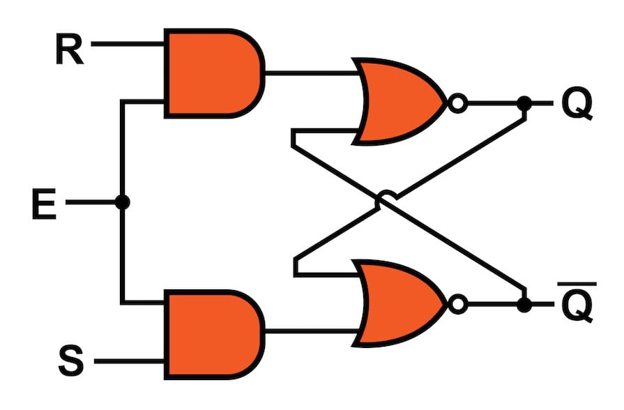
A gated latch is a useful component, but the output can change whenever the enable signal is high. This introduces a lack of precision and reliability into whatever digital interface is built around the latch. It would be better if the latch would respond to input changes only at a specific moment in time. The trouble is, once we have implemented this functionality, the latch is no longer a latch. It’s a flip-flop.
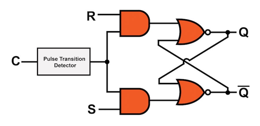
An SR flip-flop.
The pulse transition detector (PTD) converts a rising or falling edge into a short pulse. This pulse becomes the enable signal, such that the latch is enabled only for a short period of time following the transition. The latch-plus-PTD arrangement is what we call a flip-flop, and since we’re usually working with logic circuits that are governed by clock signals, the flip-flop’s enable signal is often referred to as simply the clock.
The T Flip-Flop
The essential characteristic of a flip-flop is that it changes its output state in response to a positive or negative transition on the control signal. But there is more to a flip-flop than this: we also have to define the input-to-output relationship. This is why there are different types of flip-flops; they are all sensitive to clock edges, but they perform different actions in response to the input states.
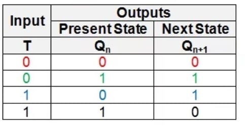
The “T” in “T flip-flop” stands for “toggle.” When you toggle a light switch, you are changing from one state (on or off) to the other state (off or on). This is equivalent to what happens when you provide a logic-high input to a T flip-flop: if the output is currently logic high, it changes to logic low; if it’s currently logic low, it changes to logic high. A logic-low input causes the T flip-flop to maintain its current output state.
Here is the same information in truth-table form:
From SR or JK to T
You can modify the input-to-output relationship of an existing flip-flop by adding logic gates and appropriate interconnections. AAC already has an abundance of information on this topic; if you want to explore the details, our article on the conversion of flip-flops is a good place to start. In this short article, I’ll simply present two ways to create a T flip-flop from an existing flip-flop.
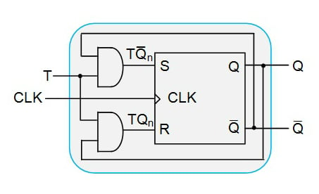
If you have an SR flip-flop, all you need is two AND gates to turn it into a T flip-flop:
The process is even easier if you’re starting with a JK flip-flop. No additional gates are required; all you need to do is connect the same input signal to both input pins:
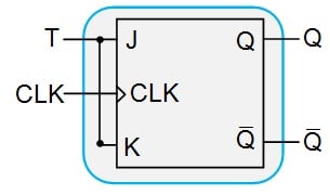
T flip-flops are handy when you need to reduce the frequency of a clock signal: If you keep the T input at logic high and use the original clock signal as the flip-flop clock, the output will change state once per clock period (assuming that the flip-flop is not sensitive to both clock edges). Thus, the output clock will be half the frequency of the input clock. If you know of a clever use for a T flip-flop, let us know in the comments.


can u explain about asynchronous active low T flip-flop
A clever usage for a T-type flip flop? I have a circuit design that uses a DPST switch to control system power. Issue is, the circuit itself resides on a PCB. Include the part where it has battery backup, I have six individual connections that are external to the PCB. I recently found an IC (FPF1320) that I might be able to use to replace the switch (it’s actually to replace another part). It was designed to control system power using an enable pin. If I can utilize a T flip flop And cleverly manipulate my power rails, I can add a button (with debouncing) and get rid of the switch. Then, my PCB will only have two external connections (battery + and -). My only problem—how I ended up on this page—is that I am in need of a T flip flop.
But anyway, there’s one creative use for a flip flop: controlling system power.