
Learn About Thevenin Theorem and Dependent Source Circuits
Learn all about Thevenin's Theorem and its application in analyzing circuits with dependent sources.
Thevenin's Theorem and its application in analyzing circuits with dependent sources.
Thevenin Theorem
When performing network analysis, Thevenin's theorem is a very helpful tool. It allows for a non-varying portion of a circuit to be replaced with a simplified design, thus simplifying the analysis of the entire network. This equivalent circuit performs the same way as the original circuit would.
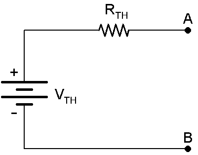
Thevenin's theorem states that any linear, two-terminal portion of a network can be replaced by a Thevenin equivalent circuit. A Thevenin equivalent circuit consists of a voltage source (VTh) in series with a resistor (RTh) where VTh is the open-circuit voltage at terminals A-B and RTh is the equivalent resistance at terminals A-B. This equivalent circuit can be seen in Figure 1 below. It is important to replace independent sources with their internal resistances when solving for RTh, i.e. current sources are replaced with open circuits and voltage sources are replaced with short circuits.
Dependent Sources and Thevenin's Theorem
Thevenin's theorem can be applied when analyzing a circuit with dependent sources. In this case, all independent sources are turned off and the RTh is calculated by applying a current source or voltage source at the open terminal. When using a voltage source, it can be assumed to be 1V for simple calculations. Using mesh analysis, find the current Io at the output. When using a current source, it can be assumed to be 1A for easy calculations as well. Nodal analysis can be used to find the voltage at the terminal. The equivalent resistance then becomes a simple Ohm's law calculation, seen in Equation 1. If RTh takes a negative value, it means the circuit is supplying power to the terminals. Then to find VTh, use mesh analysis with all independent/dependent sources included and solve for the open circuit voltage.
$$R_{Th}=\frac{1\text{ } V}{I_{o}} \; \; \text{[Equation 1]}$$
Now to apply this theory to an example problem.
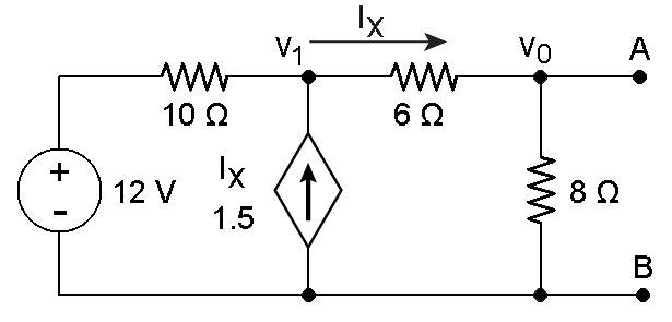
Figure 2
Solving for RTh first, redraw the circuit with the 12V source as a short circuit. Then excite the circuit using either a 1A current source or 1V voltage source at the a-b terminal. Using a current source at the a-b terminal produces the circuit in Figure 3 below.
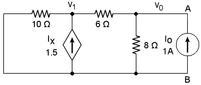
Figure 3
Now to write the nodal analysis equations.
$$\frac{V_{1}}{10\text{ }\Omega}-1.5*I_{x}+I_{x}=0\; \; \text{[Equation 2]}$$
$$\frac{V_{o}-V_{1}}{6\text{ }\Omega}+\frac{V_{o}}{8\text{ }\Omega}=1\text{ }A\; \;\; \;\;\text{ [Equation 3]}$$
where,
$$I_{x}=\frac{V_{1}-V_{o}}{6\text{ }\Omega}\; \; \; \;\; \;\; \;\; \;\; \;\;\; \;\; \;\;\text{[Equation 4]}$$
Solving for Vo yields Vo = .888V or 888.8mV. Remember that RTh = Vo / Io, so RTh is equal to 888.8 mOhms.
Next, to find VTh, replace the 12V source and remove the current source from the a-b terminal. Again, utilizing nodal analysis, the equations are as follows.
$$\frac{V_{1}}{14\text{ }\Omega}+\frac{V_{1}-12}{10\text{ }\Omega}-1.5*\frac{V_{1}}{14\text{ }\Omega}=0\; \; \text{ [Equation 5]}$$
$$\frac{V_{Th}}{8\text{ }\Omega}-\frac{V_{1}-V_{Th}}{6\text{ }\Omega}=0\; \; \; \;\; \;\; \;\; \;\; \;\;\; \;\; \;\;\; \;\; \;\;\text{[Equation 6]}$$
Solving for V1 in Equation 6 yields V1 = 1.75*VTh. Plugging this into Equation 5 and solving for VTh yields VTh = 10.66V.
This theorem allows for the simplification of resistor and source configurations into to a one source and one resistor equivalent circuit. It is commonly used with varying loads, that way the load current and power dissipation can be calculated easily.


hie why how did you took vi/14 2 times in the equation V1/14 Ω+(V1−12)/10 Ω−1.5∗V1/14 Ω=0 [Equation 5]
How can i simplify a T network with a current source given in a branch and load resistor at the other branch in between which a resistor and a dependent source is being connected in series to it?