
Understanding Current-Voltage Curves of Non-Linear Devices
This article discusses the I-V curves of passive non-linear devices such as diodes, transistors, and thyristors.
This article discusses the I-V curves of passive non-linear devices such as diodes, transistors, and thyristors.
I-V Curves of Non-Linear Devices
Current-voltage curves, or I-V curves, of electronic devices are a way of understanding how devices behave. The purpose of this technical article is to use I-V curves of ideal, linear components to better understand how non-linear devices operate.
In particular, we will be covering passive non-linear devices like diodes, transistors, and thyristors. The method of obtaining the I-V curves for passive devices is by using the linear voltage sweep method, which is discussed in detail here, in the section Obtaining I-V Curves. While external references will be provided for how these non-linear devices work, this article will only focus on the I-V curves.
Diodes
A diode is a device that allows current to flow in one direction but prevents it flowing in the reverse direction. It is a junction formed from a p-type semiconductor and an n-type semiconductor. Because the diode is a passive device, the I-V curve for a diode is obtained by a linear voltage sweep and is shown in Figure 1.
When the applied voltage across the diode is greater than zero, i.e., $$V_D > 0$$, the diode is said to be forward-biased. In forward bias, the diode current, $$I_D$$, is exponentially related to the voltage across it, $$V_D$$ and is given by the Shockley equation, shown in Figure 1. The diode in reverse bias allows very little current to pass through, and this property makes it convenient to use the diode as a switch or a rectifier.
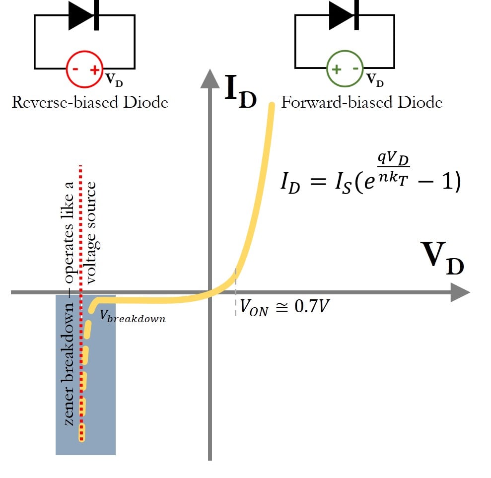
Figure 1. Current versus voltage curve for a diode. The solid line is the curve that is described by the Shockley diode equation. The highlighted area is the breakdown region of a diode, that is not described by the diode equation.
The Shockley equation only describes the diode current until the breakdown region. The breakdown region in a diode is the rapid increase of current that occurs in the reverse bias at a particular voltage, known as the breakdown voltage. While all diodes have a breakdown region, Zener diodes are special diodes that are designed to operate repeatedly in the breakdown region. To use it, the Zener diode is reverse-biased near the breakdown voltage, thereby it can allow a large range of currents to pass through the device at one particular voltage, and it is used as a passive voltage regulator.
In the context of our discussion, observe the highlighted area in Figure: the device operates like an ideal voltage source, with a straight line parallel to the current axis. The I-V curve of the diode passes through the origin, implying that there is no storage of energy in the device.
Transistors
Transistors are three-terminal semiconductor devices, where one terminal electronically controls the flow of current between the remaining two terminals.
Transistors have undergone several upgrades between 1955 and today. The earliest version of the semiconductor transistor was the Bipolar Junction Transistor (BJT). While a diode is made up of a junction of two layers, p-type and n-type semiconductors, a BJT is made up three layers which can be either n-p-n or p-n-p. A more recent common transistor is the Metal Oxide Semiconductor Field Effect Transistor (MOSFET). Recent advances in microelectronics have resulted in a new construction of the MOSFET device, known as the finFET.
Transistors are used as both analog and digital devices. As a digital device, they are used as switches and for logic gates (NOT, OR, NAND). As an analog device, they are used for amplifiers, active filters, oscillators, etc.
Because a transistor has three terminals and voltage is always measured between two points in a circuit, one terminal is assumed to be common. The characteristic curve for a transistor device is usually obtained by maintaining the voltage between one terminal with respect to the common node and sweeping the voltage between the other terminal with respect to the common node.
The circuit in Figure 10 shows, as an example, an n-type MOSFET device with three terminals: gate (G), drain (D), and source (S). The voltage $$V_{GS} = V_G – V_S$$ is fixed and the voltage between the drain and source—i.e., $$V_{DS} = V_D – V_S$$—is linearly varied. The drain current—$$I_D$$—is measured to obtain the $$I_D-V_{DS}$$ characteristic shown in Figure 10. The transistor is usually operated for positive values of $$V_{DS}$$.
![]()
Figure 2. The drain current ($$I_D$$) versus drain-to-source voltage ($$V_{DS}$$) curve for a fixed gate-to-source voltage ($$V_{GS}$$) for an n-type MOSFET device. This figure shows two regions of operation: as a resistor and as an ideal current source. The transistor is often biased (i.e., voltage values of $$V_{GS}$$ and $$V_{DS}$$ are set) so that the device can act like one of the linear components.
Observe that there are at least two regions of operation in Figure 2. The term ‘region’ here implies values for $$V_{GS}, V_{DS}$$ that produces the current $$I_D$$.
For a given set of $$V_{GS},V_{DS}$$ values, region 1 shows that the transistor device operates like a resistor because the current $$I_D$$ varies linearly with $$V_{DS}$$.
However, in region 2, the current $$I_D$$ does not change even if the voltage $$V_{DS}$$ changes, operating more like an ideal current source. The characteristic curve passes through the origin, implying that the device does not primarily store energy.
Thyristors
Thyristors are semiconductor materials that consist of four layers of alternating p-type and n-type semiconductors, i.e., they form an n-p-n-p or a p-n-p-n device.
Thyristors are three-terminal devices containing an anode, a cathode and a gate. A version of the four-layered semiconductor device, similar to a thyristor, is the silicon-controlled rectifier (SCR). A silicon-controlled rectifier is used as a bistable switch, which is a device that has two stable states and is moved from one state to another based on the input applied to the gate terminal. The thyristor, or SCR is a passive device, and its I-V curve is obtained by the voltage sweep method. It has a very interesting non-linear I-V curve, shown in Figure 3.
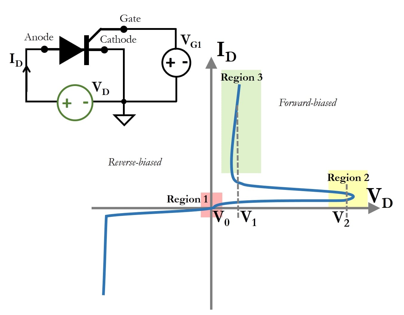
Figure 3. I-V curve of a silicon controlled rectifier, which is a version of the thyristor, showing regions of operation. When the voltage switches from $$V_0$$ to $$V_2$$ and back to $$V_1$$, the devices acts like a switch that allows any current to pass through it with only small potential drop across it.
There are three regions of interest for the forward biased I-V curve of an SCR, illustrated in Figure 3.
In region 1, the device is at voltage $$V_0$$ and it is OFF. If the voltage across an SCR changes from $$V_0$$ to $$V_2$$, there is very little current flowing through the device, and it reaches region 2. However, the operation of the device is not based on the voltage staying at $$V_2$$, but a transition from $$V_1$$ to $$V_2$$ and back to $$V_1$$. In other words, the device reaches region 3 when it is triggered by a pulse voltage that crosses $$V_2$$.
In region 3, the SCR remains at a voltage $$V_1$$ but allows any current to flow through it. While the curve shown in region 3 is similar to a voltage source, the SCR is a passive device; for small values of $$V_1$$, it is operated like a switch. A switch is a device that closes any circuit, thereby allowing any current to pass through without a significant potential drop across it. The device will turn off again only when the voltage is back at $$V_0$$.
SCRs are commonly used as programmable electrical swtiches for circuits operating with high voltages. The I-V curve of the thyristor passes through the origin, similar to other passive non-linear devices.
Summary of Understanding I-V Curves of Non-Linear Devices
The table below summarizes the discussion on the I-V curves of non-linear devices:
| Devices | Requires Power? | I-V Method | Commonly used as? | Passes through Origin? |
| Diode | Yes | Voltage Sweep | Voltage regulator (Zener) | Yes |
| Transistor | Yes | Voltage Sweep | Current source or a resistor (analog) | Yes |
| Thyristor | Yes | Voltage Sweep | Bistable switch | Yes |


Hello,
Very nice article!
In my opinion there is a point that may lead to misinterpretation. The fact that a device I/V curve passes through the origin is not precisely because the device does not storage energy. The I/V curve for an energy storing device, such as the capacitor, does not make much sense since the I/V curve is obtained for a DC condition.
In my opinion, a better interpretation would be to say that if the curve does not hit the second or fourth quadrant, then it corresponds to a device incapable of providing DC energy. Being in the second or fourth quadrant means that at some operating point, current and voltage have different signs, which is a feature of devices that generate (instead of dissipate) energy. On the other hand, if the curve has a negative slope at some point, then it acts - locally - with a negative resistance (e.g., tunnel diodes), since the slope is related to the resistance, but it does not mean that the device is capable of providing DC energy unless it is in the second or fourth quadrant.
Transistors are considered active devices but their I/V curves go through the origin. This is because they only dissipate energy (only first or third quadrant), but since they can be configured to act as controlled sources, then they are active devices. It is possible to produce an I/V curve with negative slope at some point using active devices along with power sources.
So summarizing, I/V curves of energy-consuming devices (passive or active) only pass through first and third quadrant. A necessary (but not sufficient) condition for an I/V curve to be only in the first or third quadrant is to go through the origin.
Hope it helps 😉
- Angel
Error: “While the curve shown in region 3 is similar to a current source,”
Change this to “While the curve shown in region 3 is similar to a voltage source,”
Thanks,
-Krish