
Understanding Linear-Phase Filters
Linear phase response, also known as constant group delay, is an important property in some filter applications.
Linear phase response, also known as constant group delay, is an important property in some filter applications.
Related Information
In most filter discussions, the focus is on amplitude. If we need antialiasing for an ADC, we need a low-pass filter, i.e., a circuit that maintains (or increases) the amplitude of lower-frequency signals and reduces the amplitude of higher-frequency signals. If we are removing the DC offset from an audio signal, we use a high-pass filter, but we have to ensure that the corner frequency is low enough to avoid reducing the amplitude of signal frequencies that we want to hear.
It’s important to remember, though, that filters affect not only the amplitude of a signal but also the phase.
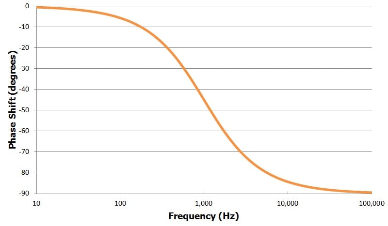
A basic resistor–capacitor (RC) low-pass filter, for example, will shift an output sinusoid by up to 90° relative to the input sinusoid. The “up to” qualifier in the previous sentence is important—the actual phase shift depends on the frequency of the signal passing through the filter, as shown in the following plot of phase shift vs. frequency for an RC low-pass filter with a cutoff frequency of 1 kHz.
Now consider a situation in which a filter will see signals composed of various different frequencies that work together. Problems could arise if these different frequencies experience different delays. Here are two examples:
- Audio applications: Frequencies representing different pitches must remain synchronized to ensure proper sound reproduction.
- Digital communications: The sinusoidal harmonic frequencies that constitute a square wave must experience constant delay to avoid distortion of the digital signal.
At this point the situation might seem hopeless—looking at the plot above, we see clearly that the phase shift changes drastically according to frequency. But there is a critical point that changes everything: we have to remember that the time-delay equivalent of a particular phase shift varies according to frequency. Consider the following diagram:
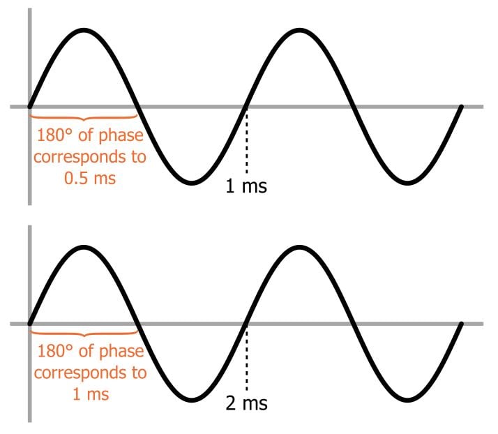
What we see here are two sine waves, one at 1 kHz (i.e., period = 1 ms) and one at 500 Hz (i.e., period = 2 ms). A particular phase shift—the diagram uses 180° as an example—corresponds to a different amount of time for each frequency: a different frequency means a different period, and a phase shift corresponds to a specified proportion of the period.
It follows, then, that maintaining synchronization between the various frequency components of a signal does not mean enforcing a constant phase shift, because a constant phase shift would result in different temporal delays.
To achieve equal temporal delays for all the frequencies, we need every frequency to have a different phase shift—namely, a phase shift that results in the same delay for every frequency. More specifically, we need a phase-shift response that increases linearly with frequency; this makes sense, because as the frequency increases a fixed phase shift corresponds to a gradually diminishing length of time, and thus we need more phase shift to compensate.
An ideal linear-phase filter, then, exhibits phase shift that increases linearly with frequency, and it thereby provides constant temporal delay (this applies primarily to the frequencies within the passband, i.e., the frequencies of interest). Group delay is proportional to the derivative of the phase response with respect to frequency; the derivative of a linear function is a constant, which explains why a linear phase response is also referred to as constant group delay. A well-known topology that is optimized for linear phase is the Bessel filter.


I would recommend this article “Linear phase response, also known as constant group delay” to all who is interested in understanding importance of Linear phase.
Excellent article!!
One of my friends presented it to me: https://leocblog.wordpress.com/2020/06/15/my-friend-ju/
Regards,
Leonardo Cardillo
https://www.linkedin.com/in/leonardocardillo