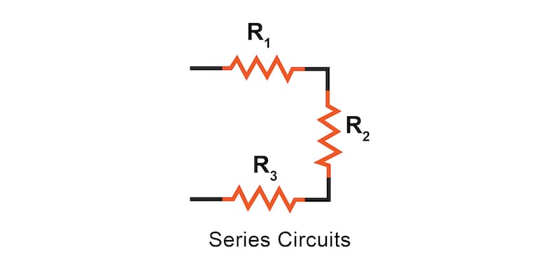
In a series circuit, all components are connected end-to-end to form a single path for current flow. The total resistance in a series circuit is equal to the sum of the individual resistors, and the total voltage drop is equal to the sum of the individual voltage drops across those resistors.
In this introduction to series resistance circuits, we will explain these three key principles you should understand:
We’ll examine these three principles using the series circuit consisting of three resistors and a single battery, as illustrated in Figure 1.
In a series circuit, the same amount of current flows through each component in the circuit. This is because there is only one path for the current flow. Since electric charge flows through conductors like marbles in a tube, the rate of flow (marble speed) at any point in the circuit (tube) at any specific point in time must be equal.
An important caveat to Ohm’s law is that all quantities (voltage, current, resistance, and power) must relate to each other in terms of the same two points in a circuit. Before we examine the more complex series circuit in Figure 1, let’s examine this concept for a single resistor circuit.
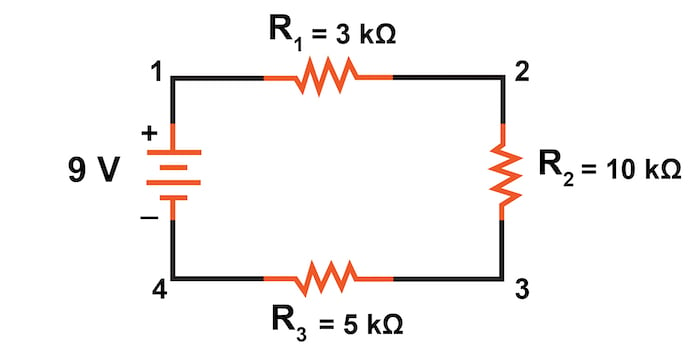
For this initial analysis, we will evaluate the current and voltage for the single resistor circuit in Figure 2.

Since points 1 and 2 are connected together with the wire of negligible resistance, as are points 3 and 4, we can say that point 1 is electrically common to point 2 and that point 3 is electrically common to point 4.
Since the circuit has 9 V of electromotive force between points 1 and 4 (directly across the battery), it must also drop 9 V between points 2 and 3 (directly across the resistor). This is because Kirchhoff’s Voltage law states that the sum of all voltages in a loop must equal zero.
Therefore, we can apply Ohm’s Law (I = V/R) to the current through the resistor because we know the voltage (V) across the resistor and the resistance (R) of that resistor. All terms (V, I, R) apply to the same two points in the circuit and to that resistor, so we can use Ohm’s law formula with no reservation:
$$I = \frac{V}{R}$$
$$I = \frac{9 \text{ V}}{3 \text{ k}\Omega} = 3 \text{ mA}$$
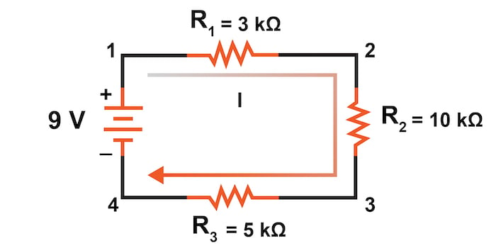
Returning to Figure 1’s circuit, we can see that the polarity of the 9 V battery will again result in a current, I, that will flow in a clockwise direction from point 1 to 2 to 3 to 4 and back to 1. This concept is illustrated in Figure 3.
However, we have one source of voltage and three resistances. From there, we might consider how we use Ohm’s law here.
In the three-resistor example circuit of Figure 3, we have 9 V between points 1 and 4, which is the amount of electromotive force driving the current through the series combination of R1, R2, and R3. However, we cannot take the value of 9 V and divide it by 3 kΩ, 10 kΩ, or 5 kΩ to try to find a current value because we don’t know how much voltage is across any one of those resistors individually.
The voltage value of 9 V is the total quantity for the whole circuit, whereas the values of 3 kΩ, 10 kΩ, or 5 kΩ are individual quantities for individual resistors. If we were to plug a value for total voltage into an Ohm’s law equation with a value for individual resistance, the result would not relate accurately to any quantity in the real circuit.
For R1, Ohm’s law will relate the amount of voltage across R1 with the current through R1, given R1‘s resistance of 3 kΩ:
$$ I_{R1} = \frac{V_{R1}}{3 \text{ k}\Omega} $$
$$ E_{R1} = I_{R1} \cdot 3 \text{ k}\Omega $$
However, since we don’t know the voltage across R1 (only the total voltage supplied by the battery across the three-resistor series combination) and we don’t know the current through R1, we can’t do any calculations with either formula. The same goes for R2 and R3—we can apply Ohm’s law equations if and only if all terms are representative of their respective quantities between the same two points in the circuit.
So what can we do? We know the voltage of the source (9 V) applied across the series combination of R1, R2, and R3, and we know the resistance of each resistor. However, since those quantities aren’t in the same context, we can’t use Ohm’s law to determine the circuit current.
If only we knew what the total resistance was for the circuit, then we could calculate the total current with our value for total voltage (I = V/R).
This brings us to the second principle of series circuits: the total resistance of a series circuit is equal to the sum of the individual resistances.
This should intuitively make sense, basically, the more resistors in series that the current must flow through, the more difficult it will be for the current to flow.
In the example problem, we had a 3 kΩ, 10 kΩ, and 5 kΩ resistors in series, giving us a total resistance of 18 kΩ:
$$R_{total} = R_1 + R_2 + R_3$$
$$R_{total} = 3 \text{ k}\Omega + 10 \text{ k}\Omega + 5 \text{ k}\Omega$$
$$R_{total} = 18 \text{ k}\Omega$$
In essence, we’ve calculated the total equivalent resistance of R1, R2, and R3 combined. Knowing this, we can redraw the circuit (Figure 4) with a single equivalent resistor representing the series combination of R1, R2, and R3:
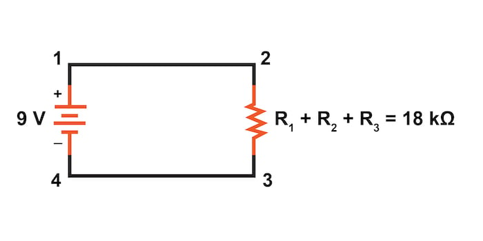
With all those calculations completed, we now have all the necessary information to calculate the circuit current for Figure 4 since we have the voltage between points 1 and 4 (9 V) and the resistance between points 1 and 4 (18 kΩ).
$$I_{total} = \frac{V_{total}}{R_{total}}$$
$$I_{total} = \frac{9 \text{ V}}{18 \text{ k}\Omega} = 500 \space \mu \text{A}$$
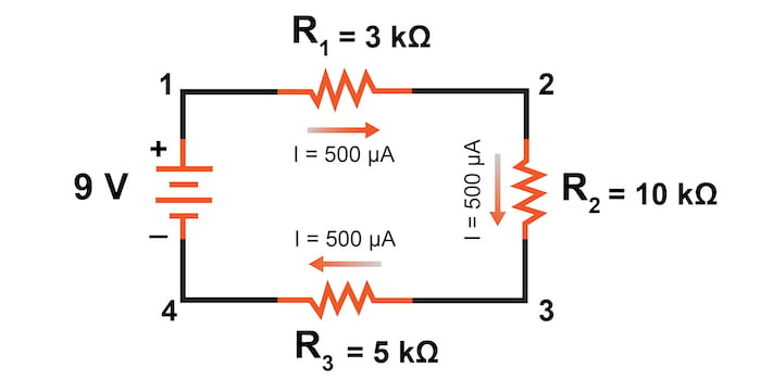
Knowing that current is equal through all components of a series circuit (and we just determined the current through the battery), we can go back to our original circuit schematic of Figure 1 and note the current through each component, shown in Figure 5 as:
Now that we know the amount of current through each resistor, we can use Ohm’s law to determine the voltage drop across each one (applying Ohm’s law in its proper context):
$$V_{R1} = I_{R1} \cdot R_1 = (500 \space \mu \text{A}) \cdot (3 \text{ k} \Omega) = 1.5 \text{ V}$$
$$V_{R2} = I_{R2} \cdot R_2 = (500 \space \mu \text{A}) \cdot (10 \text{ k} \Omega) = 5.0 \text{ V}$$
$$V_{R3} = I_{R3} \cdot R_3 = (500 \space \mu \text{A}) \cdot (5 \text{ k} \Omega) = 2.5 \text{ V}$$
Notice that sum of the voltage drops (1.5 + 5.0 + 2.5 = 9.0 V) is equal to the battery (supply) voltage of 9 V.
This is the third principle of series circuits—the total voltage drop in a series circuit equals the sum of the individual voltage drops.
Below find more ways to learn more about series circuits and the use of Ohm's law:
Calculators:
Worksheets:
Video Lectures and Tutorials:
Technical Articles:

In Partnership with Samtec


by Aaron Carman

by Duane Benson


The Engineering Series In Electrical Circuit 1 written by Nedaa Alfukahaa