The proper name for the circuit in Figure 1 is an astable multivibrator.
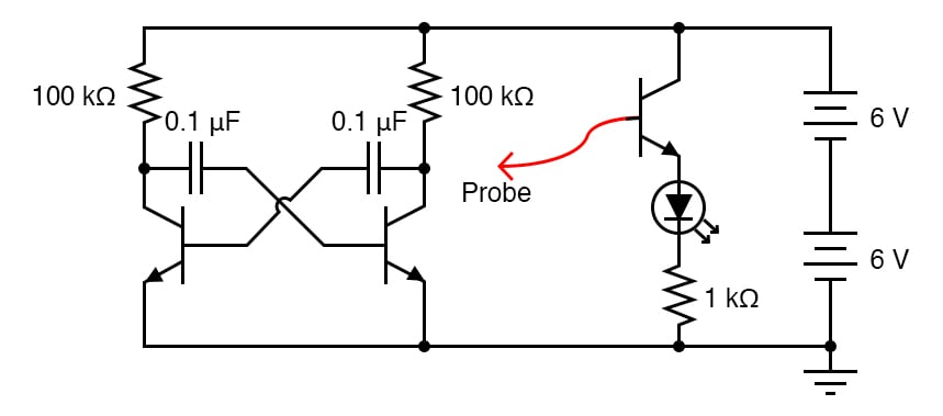
It is a simple, free-running oscillator circuit timed by the values of the resistors, capacitors, and power supply voltage. Unfortunately, its output waveform is distorted, neither sine wave nor square wave. However, for the simple purpose of making an audio tone, distortion doesn’t matter much.
The multivibrator itself is just two transistors, two resistors, and two cross-connecting capacitors in the left portion of Figure 1. The capacitors provide positive feedback in the circuit to keep it oscillating. The third transistor, shown at the right in Figure 1, is there to drive an LED (light-emitting diode) as a visual indicator of oscillator action.
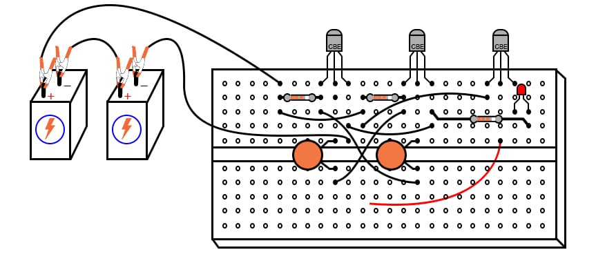
Step 1: Build the circuit illustrated in the schematic of Figure 1 and the breadboard implementation of Figure 2.
With a 12 V supply, 100 kΩ resistors, and 0.1 µF capacitors, the oscillation frequency will be in the low audio range.
Step 2: You may listen to this signal with the audio detector connected with one test probe to the ground and the other to one of the transistor’s collector terminals. We recommend placing a 1 MΩ resistor in series with the audio detector to minimize both circuit loading effects and headphone volume, as illustrated in Figure 3.
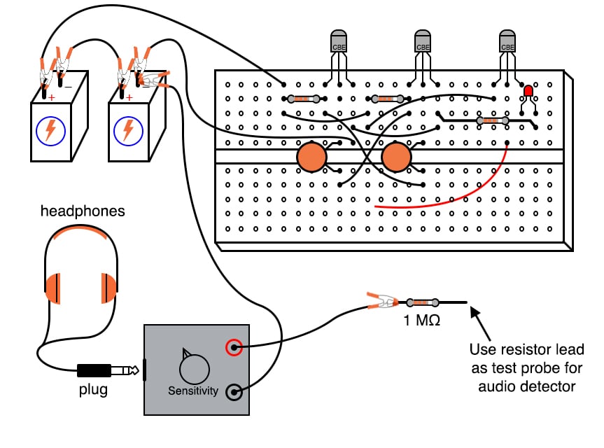
Of course, you could also observe the waveforms and frequency if you have an oscilloscope.
Step 3: Use the probe wire connected to the base of this common-emitter amplifier to detect voltage at different parts of the circuit with respect to the ground. Given the low oscillating frequency of this multivibrator circuit, you should be able to see the LED blink rapidly with the probe wire connected to the collector terminal of either multivibrator transistor.
You may notice that the LED fails to blink with its probe wire touching the base of either multivibrator transistor, yet the audio detector (or oscilloscope) tells you there is an oscillating voltage there. Why is this?
The LED’s common-collector transistor amplifier is a voltage follower, meaning that it doesn’t amplify voltage. Thus, if the voltage under test is less than the minimum required by the LED to light up, it will not glow. Since the forward-biased base-emitter junction of an active transistor drops only about 0.7 V, there is an insufficient voltage at either transistor base to energize the LED. The audio detector, being extraordinarily sensitive, though, detects this low voltage signal easily.
Step 4: Substitute lower-value resistors in place of the two 100 kΩ units shown. What happens to the oscillation frequency when you do so? We recommend using resistors at least 1 kΩ in size to prevent excessive transistor current.
Step 5: One shortcoming of many oscillator circuits is their dependence on a minimum amount of power supply voltage. Too little voltage, and the circuit ceases to oscillate. This circuit is no exception. Experiment with lower supply voltages and determine the minimum voltage necessary for oscillation, as well as experience the effect supply voltage change has on the oscillation frequency.
One shortcoming specific to this circuit is the dependence on mismatched components for successful starting. For the circuit to begin oscillating, one transistor must turn on before the other one. Usually, there is enough mismatch in the various component values to enable this to happen, but it is possible for the circuit to freeze at a stable operating point and fail to oscillate at power-up. If this happens, try different components (same values, but different units) in the circuit.
Learn more about the fundamentals behind this project in the resources below.
Textbook:
Worksheets:

In Partnership with Future Electronics

by Jake Hertz

by Robert Keim

by Duane Benson