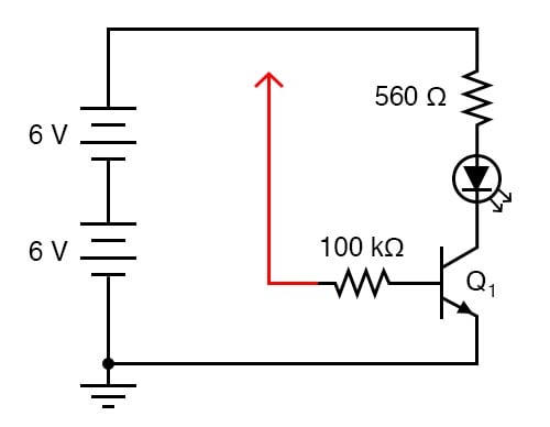
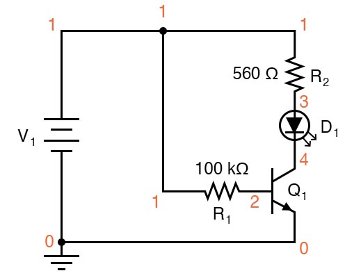
Transistors are used as switching devices in digital and analog circuits. In this project, the circuit of Figure 1 will be used to demonstrate how an NPN bipolar junction transistor (BJT) can be used to switch a light-emitting diode (LED) on and off.
Resistor values are not critical for this experiment. Neither is the particular LED selected.
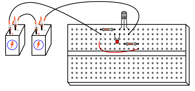
Step 1: Build the circuit illustrated in Figures 1 and 2.
Pay careful attention to the correct connections for the NPN transistor. The red wire shown in Figure 1—terminating in an arrowhead and connected to one end of the 100 kΩ resistor—is intended to remain loose so that you may touch it momentarily at other points in the circuit.
Step 2: If you touch the end of the loose wire to any point in the circuit more positive than it, such as the positive side of the DC power source, the LED should light up. It takes 20 mA to fully illuminate a standard LED. This behavior should strike you as interesting because the 100 kΩ resistor to which the loose wire is attached restricts current through it to a far lesser value than 20 mA.
At most, a total voltage of 12 V across a 100 kΩ resistance yields a current of only 0.12 mA or 120 µA. The connection made by your touching the wire to a positive point in the circuit conducts far less current than 1 mA. Yet through its amplifying action, the transistor is able to control a much greater current through the LED.
Step 2: Try using an ammeter to connect the loose wire to the positive side of the power source, as illustrated in Figure 3.
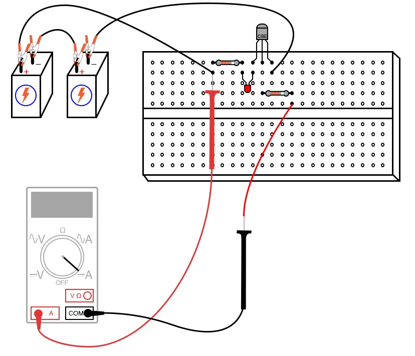
You may have to select the most sensitive current range on the meter to measure this small flow into the base of the NPN transistor.
Step 3: After measuring this controlling base current, try measuring the LED’s current (the controlled current) and comparing magnitudes. Don’t be surprised if you find a ratio in excess of 200 (the controlled current is 200 times as great as the controlling current). As you can see, the transistor is acting as a kind of electrically-controlled switch, switching current on and off to the LED at the command of a much smaller current signal conducted through its base terminal.
Step 4: To further illustrate just how minuscule the controlling current is, remove the loose wire from the circuit. From there, try bridging the unconnected end of the 100 kΩ resistor to the power source’s positive pole with two fingers of one hand, as shown in Figure 4.
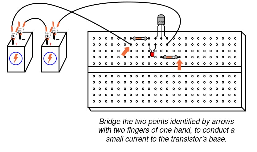
You may need to wet the ends of those fingers to maximize conductivity.
Step 5: Try varying the contact pressure of your fingers with these two points in the circuit to vary the amount of resistance in the controlling current’s path. Can you vary the brightness of the LED by doing so? What does this indicate about the transistor’s ability to act as more than just a switch; i.e. as a variable amplifier?
You can simulate this operation of this bipolar junction transistor circuit using the illustration of Figure 5 and the netlist below.
Netlist (make a text file containing the following text, verbatim):
Transistor as a switch
v1 1 0
r1 1 2 100k
r2 1 3 560
d1 3 4 mod2
q1 4 2 0 mod1
.model mod1 npn bf=200
.model mod2 d is=1e-28
.dc v1 12 12 1
.print dc v(2,0) v(4,0) v(1,2) v(1,3) v(3,4)
.end
In this simulation, the voltage drop across the 560 Ω resistor v(1,3) turns out to be 10.26 V, indicating a LED current of 18.32 mA by Ohm’s Law (I = V/R). The voltage drop of resistor R1 ends up being 11.15 V, which across 100 kΩ, gives a current of only 111.5 µA. Obviously, a small current is exerting control over a much larger current in this circuit.
In case you were wondering, the is=1e-28 parameter in the diode’s .model line is there to make the diode act more like an LED with a higher forward voltage drop.
Learn more about the fundamentals behind this project in the resources below.
Textbook:
Worksheets:

In Partnership with MacroFab

by Swissbit

by Jake Hertz


