Zener diodes are frequently used as voltage regulating devices because they act to clamp the voltage drop across themselves at a predetermined level. In this project, you will build and test a simple Zener diode voltage regulator, as illustrated in Figure 1, for a number of different supply voltages.
Any low-voltage Zener diode is appropriate for this experiment. The 1N4742 model listed here (Zener voltage = 12 V) is but one suggestion. Whatever diode model you choose, I highly recommend one with a Zener voltage rating greater than the voltage of a single battery for a maximum learning experience. It is important that you see how a Zener diode functions when exposed to a voltage less than its breakdown rating.
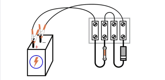
Step 1: Build the simple circuit shown in the circuit schematic of Figure 2 and illustrated in Figure 3.
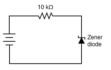
Be sure to connect the Zener diode in a reverse-bias orientation (cathode positive and anode negative).
Step 2: Measure the voltage across the diode with one battery as a power source. Record this voltage drop for future reference.
Step 3: Measure and record the voltage drop across the 10 kΩ resistors.
Step 4: Modify the circuit by connecting two 6 V batteries in series for a 12 V total power source voltage.
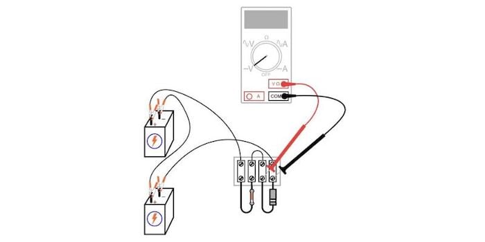
Step 5: Re-measure the diode’s voltage drop, as well as the resistor’s voltage drop, with a voltmeter, as illustrated above in Figure 1.
Step 6: Connect three, then four, and 6 V batteries together in series, forming an 18 V and 24 V power source, respectively. Measure and record the diode and resistor’s voltage drops for each new power supply voltage.
Questions to consider:
The reverse-biased Zener diode clamps the voltage drop at their breakdown voltage. Above this Zener voltage, the Zener diode conducts a lot more current so that any excess voltage supplied by the power source is dropped across the 10 kΩ series resistor.
However, it is important to note that a Zener diode cannot make up for a deficiency in source voltage (unlike some types of voltage regulators). For instance, this 12 V Zener diode does not drop 12 V when the power source is only 6 V. It is helpful to think of a Zener diode as a voltage limiter that establishes a maximum voltage drop but not a minimum voltage drop.
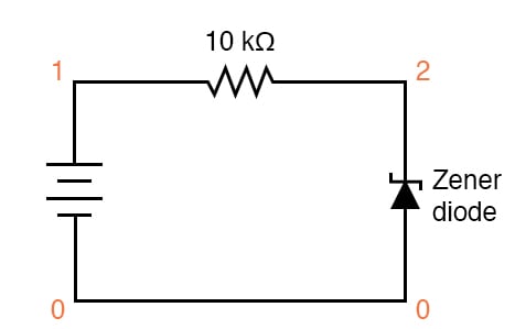
A zener diode may be simulated in SPICE with a normal diode by setting the reverse breakdown parameter (bv = 12) to the desired zener breakdown voltage. Figure 4 is an illustration of a Zener diode circuit schematic with node numbers added for SPICE simulation.
Netlist (make a text file containing the following text, verbatim):
Zener diode
v1 1 0
r1 1 2 10k
d1 0 2 mod1
.model mod1 d bv=12
.dc v1 18 18 1
.print dc v(2,0)
.end
Learn more about the fundamentals behind this project in the resources below.
Textbook:
Worksheets:
In Partnership with 4PCB


by Siglent

by Jake Hertz

by Aaron Carman

