If we add a voltage divider to the negative feedback wiring so that only a fraction of the output voltage is fed back to the inverting input instead of the full amount, the output voltage will be a multiple of the input voltage (please bear in mind that the power supply connections to the op-amp have been omitted once again for simplicity’s sake):
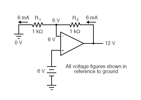
If R1 and R2 are both equal and Vin is 6 volts, the op-amp will output whatever voltage is needed to drop 6 volts across R1 (to make the inverting input voltage equal to 6 volts, as well, keeping the voltage difference between the two inputs equal to zero). With the 2:1 voltage divider of R1 and R2, this will take 12 volts at the output of the op-amp to accomplish.
Another way of analyzing this circuit is to start by calculating the magnitude and direction of current through R1, knowing the voltage on either side (and therefore, by subtraction, the voltage across R1), and R1s resistance. Since the left-hand side of R1 is connected to ground (0 volts) and the right-hand side is at a potential of 6 volts (due to the negative feedback holding that point equal to Vin), we can see that we have 6 volts across R1. This gives us 6 mA of current through R1 from right to left. Because we know that both inputs of the op-amp have extremely high impedance, we can safely assume they won’t add or subtract any current through the divider. In other words, we can treat R1 and R2 as being in series with each other: the current flowing through R1 must be the same with R2. Knowing the current through R2 and the resistance of R2, we can calculate the voltage across R2 (6 volts), and its polarity. Counting up voltages from ground (0 volts) to the right-hand side of R2, we arrive at 12 volts on the output.
Upon examining the last illustration, one might wonder, “where does that 6 mA of current go?” Since the output voltage is positive, current flows from the positive side of the DC power supply, through the output pin of the op amp, through R2, through R1, to ground. Using the null detector/potentiometer model of the op-amp, the current path looks like this:
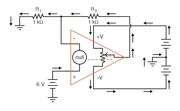
The 6 volt signal source does not have to supply any current for the circuit: it merely commands the op-amp to balance voltage between the inverting (-) and noninverting (+) input pins, and in so doing produce an output voltage that is twice the input due to the dividing effect of the two 1 kΩ resistors.
We can change the voltage gain of this circuit, overall, just by adjusting the values of R1 and R2 (changing the ratio of output voltage that is fed back to the inverting input). Gain can be calculated by the following formula:
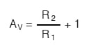
Note that the voltage gain for this design of amplifier circuit can never be less than 1. If we were to lower R2 to a value of zero ohms, our circuit would be essentially identical to the voltage follower, with the output directly connected to the inverting input. Since the voltage follower has a gain of 1, this sets the lower gain limit of the noninverting amplifier. However, the gain can be increased far beyond 1, by increasing R2 in proportion to R1.
Also note that the polarity of the output matches that of the input, just as with a voltage follower. A positive input voltage results in a positive output voltage, and vice versa (with respect to ground). For this reason, this circuit is referred to as a noninverting amplifier.
Just as with the voltage follower, we see that the differential gain of the op-amp is irrelevant, so long as its very high. The voltages and currents in this circuit would hardly change at all if the op-amp’s voltage gain were 250,000 instead of 200,000. This stands as a stark contrast to single-transistor amplifier circuit designs, where the Beta of the individual transistor greatly influenced the overall gains of the amplifier. With negative feedback, we have a self-correcting system that amplifies voltage according to the ratios set by the feedback resistors, not the gains internal to the op-amp.
Let’s see what happens if we retain negative feedback through a voltage divider, but apply the input voltage at a different location:
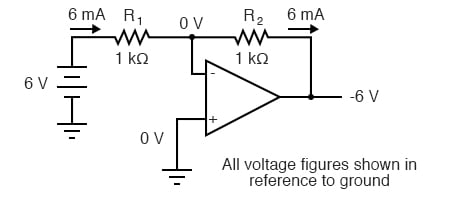
By grounding the noninverting input, the negative feedback from the output seeks to hold the inverting input’s voltage at 0 volts, as well. For this reason, the inverting input is referred to in this circuit as a virtual ground, being held at ground potential (0 volts) by the feedback, yet not directly connected to (electrically common with) ground. The input voltage this time is applied to the left-hand end of the voltage divider (R1 = R2 = 1 kΩ again), so the output voltage must swing to -6 volts in order to balance the middle at ground potential (0 volts). Using the same techniques as with the noninverting amplifier, we can analyze this circuit’s operation by determining current magnitudes and directions, starting with R1, and continuing on to determining the output voltage.
We can change the overall voltage gain of this circuit, overall, just by adjusting the values of R1 and R2 (changing the ratio of output voltage that is fed back to the inverting input). Gain can be calculated by the following formula:
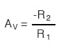
Note that this circuit’s voltage gain can be less than 1, depending solely on the ratio of R2 to R1. Also note that the output voltage is always the opposite polarity of the input voltage. A positive input voltage results in a negative output voltage, and vice versa (with respect to ground). For this reason, this circuit is referred to as an inverting amplifier. Sometimes, the gain formula contains a negative sign (before the R2/R1 fraction) to reflect this reversal of polarities.
These two amplifier circuits we’ve just investigated serve the purpose of multiplying or dividing the magnitude of the input voltage signal. This is exactly how the mathematical operations of multiplication and division are typically handled in analog computer circuitry.
REVIEW:

In Partnership with Würth Elektronik eiSos GmbH & Co. KG


by Jake Hertz


by Duane Benson

