If we connect the output of an op-amp to its inverting input and apply a voltage signal to the noninverting input, we find that the output voltage of the op-amp closely follows that input voltage (I’ve neglected to draw in the power supply, +V/-V wires, and ground symbol for simplicity):
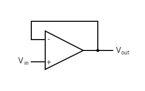
As Vin increases, Vout will increase in accordance with the differential gain. However, as Vout increases, that output voltage is fed back to the inverting input, thereby acting to decrease the voltage differential between inputs, which acts to bring the output down. What will happen for any given voltage input is that the op-amp will output a voltage very nearly equal to Vin, but just low enough so that there’s enough voltage difference left between Vin and the (-) input to be amplified to generate the output voltage.
The circuit will quickly reach a point of stability (known as equilibrium in physics), where the output voltage is just the right amount to maintain the right amount of differential. Taking the op-amp’s output voltage and coupling it to the inverting input is a technique known as negative feedback, and it is the key to having a self-stabilizing system (this is true not only of op-amps, but of any dynamic system in general). This stability gives the op-amp the capacity to work in its linear (active) mode, as opposed to merely being saturated fully “on” or “off” as it was when used as a comparator, with no feedback at all.
Because the op-amp’s gain is so high, the voltage on the inverting input can be maintained almost equal to Vin. We can write an equation relating the output voltage to the input voltage and the gain, G:
$$V_{out} = G · (V_{in} - V_{out})$$
Then, solving for the output voltage, we get the following:
$$V_{out} = \frac{V_{in}}{1 + (\frac{1}{G})}$$
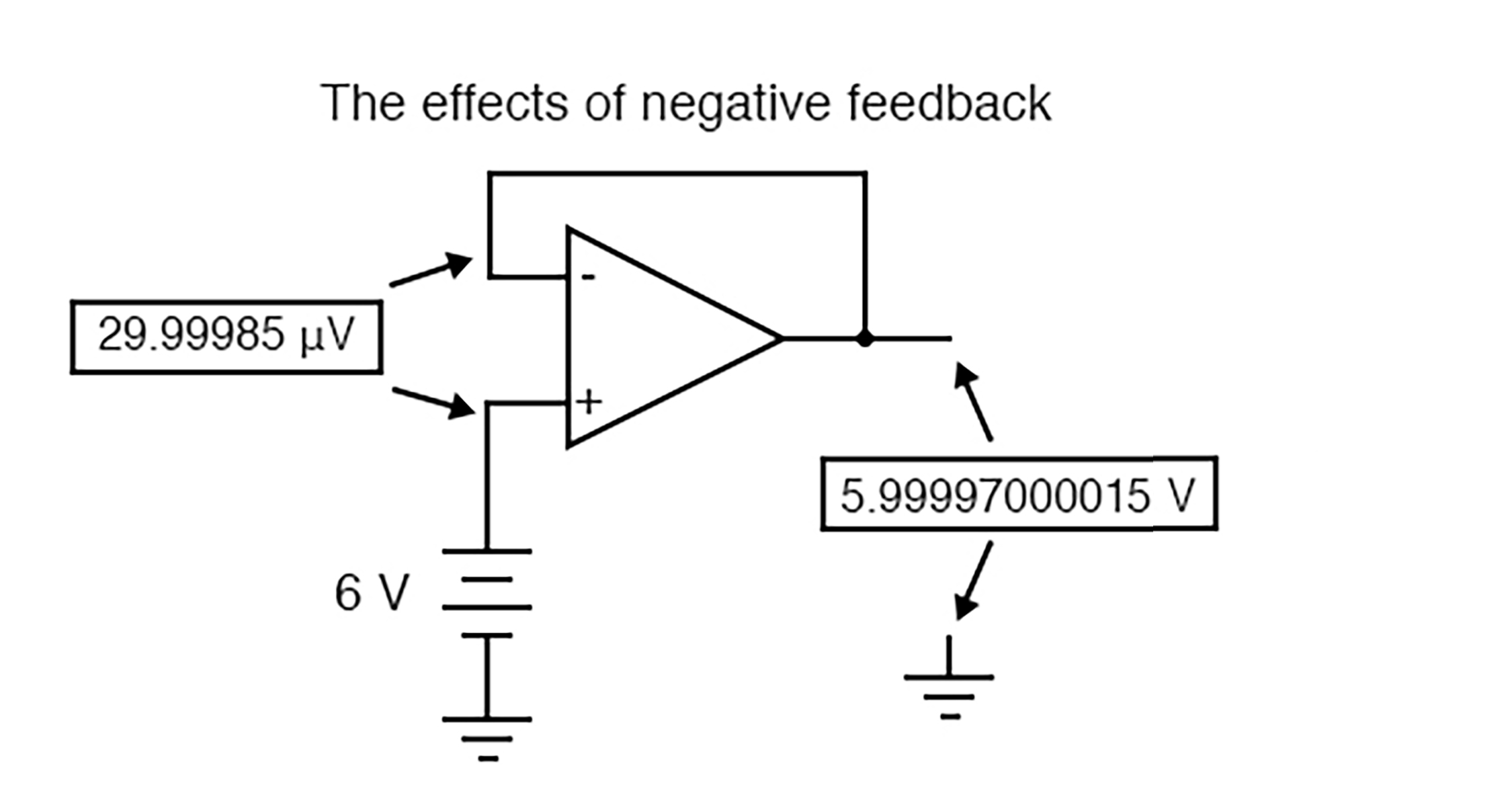
Let’s say that our op-amp has a differential voltage gain of 200,000 and Vin equals 6 V, we can calculate the output voltage using our equation:
$$V_{out} = \frac{6}{1 + (\frac{1}{20,000})} = 5.999700015 V$$
This creates just enough differential voltage (6 V - 5.99997000015 V = 29.99985 µV) to cause 5.99997000015 volts to be manifested at the output terminal, and the system holds there in balance. As you can see, 29.99985 µV is not a lot of differential, so for practical calculations, we can assume that the differential voltage between the two input wires is held by negative feedback exactly at 0 volts.
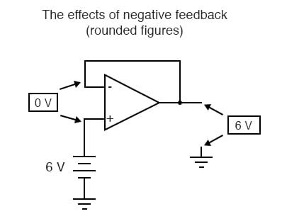
One great advantage in using an op-amp with negative feedback is that the actual voltage gain of the op-amp doesn’t matter, so long as its very large. If the op-amp’s differential gain were 250,000 instead of 200,000, all it would mean is that the output voltage would hold just a little closer to Vin (less differential voltage needed between inputs to generate the required output). In the circuit just illustrated, the output voltage would still be (for all practical purposes) equal to the non-inverting input voltage. Op-amp gains, therefore, do not have to be precisely set by the factory in order for the circuit designer to build an amplifier circuit with precise gain. Negative feedback makes the system self-correcting. The above circuit as a whole will simply follow the input voltage with a stable gain of 1.
Going back to our differential amplifier model, we can think of the operational amplifier as being a variable voltage source controlled by an extremely sensitive null detector, the kind of meter movement or other sensitive measurement device used in bridge circuits to detect a condition of balance (zero volts). The “potentiometer” inside the op-amp creating the variable voltage will move to whatever position it must to “balance” the inverting and non-inverting input voltages so that the “null detector” has zero voltage across it:
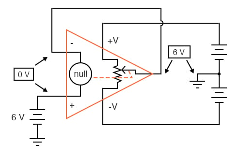
As the “potentiometer” will move to provide an output voltage necessary to satisfy the “null detector” at an “indication” of zero volts, the output voltage becomes equal to the input voltage: in this case, 6 volts. If the input voltage changes at all, the “potentiometer” inside the op-amp will change position to hold the “null detector” in balance (indicating zero volts), resulting in an output voltage approximately equal to the input voltage at all times.
This will hold true within the range of voltages that the op-amp can output. With a power supply of +15V/-15V, and an ideal amplifier that can swing its output voltage just as far, it will faithfully “follow” the input voltage between the limits of +15 volts and -15 volts. For this reason, the above circuit is known as a voltage follower. Like its one-transistor counterpart, the common-collector (“emitter-follower”) amplifier, it has a voltage gain of 1, a high input impedance, a low output impedance, and a high current gain. Voltage followers are also known as voltage buffers, and are used to boost the current-sourcing ability of voltage signals too weak (too high of source impedance) to directly drive a load. The op-amp model shown in the last illustration depicts how the output voltage is essentially isolated from the input voltage, so that current on the output pin is not supplied by the input voltage source at all, but rather from the power supply powering the op-amp.
It should be mentioned that many op-amps cannot swing their output voltages exactly to +V/-V power supply rail voltages. The model 741 is one of those that cannot: when saturated, its output voltage peaks within about one volt of the +V power supply voltage and within about 2 volts of the -V power supply voltage. Therefore, with a split power supply of +15/-15 volts, a 741 op-amp’s output may go as high as +14 volts or as low as -13 volts (approximately), but no further. This is due to its bipolar transistor design. These two voltage limits are known as the positive saturation voltage and negative saturation voltage, respectively. Other op-amps, such as the model 3130 with field-effect transistors in the final output stage, have the ability to swing their output voltages within millivolts of either power supply rail voltage. Consequently, their positive and negative saturation voltages are practically equal to the supply voltages.
REVIEW:
RELATED WORKSHEET:

In Partnership with Geehy Semiconductor

by Laird


by Duane Benson

by Robert Keim


How does output come as 5.999970000149999???How did you assume this value ??