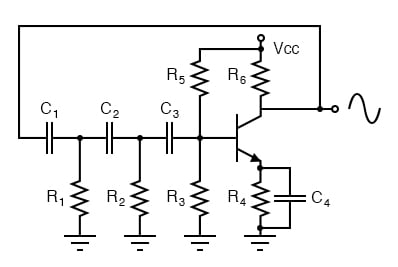
Phase shift oscillator. R1C1, R2C2, and R3C3 each provide 60° of phase shift.
The phase shift oscillator of the figure above produces a sine wave output in the audio frequency range. Resistive feedback from the collector would be negative feedback due to 180° phasing (base to collector phase inversion). However, the three 60° RC phase shifters ( R1C1, R2C2, and R3C3) provide an additional 180° for a total of 360°. This in-phase feedback constitutes positive feedback. Oscillations result if transistor gain exceeds feedback network losses.
A varactor or variable capacitance diode with a nonlinear capacitance vs frequency characteristic distorts the applied sinewave f1 in the figure below, generating harmonics, f3.
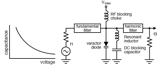
Varactor diode, having a nonlinear capacitance vs voltage characteristic, serves in frequency multiplier.
The fundamental filter passes f1, blocking the harmonics from returning to the generator. The choke passes DC and blocks radio frequencies (RF) from entering the Vbias supply. The harmonic filter passes the desired harmonic, say the 3rd, to the output, f3. The capacitor at the bottom of the inductor is a large value, low reactance, to block DC but ground the inductor for RF. The varicap diode in parallel with the inductor constitutes a parallel resonant network. It is tuned to the desired harmonic. Note that the reverse bias, Vbias, is fixed. The varicap multiplier is primarily used to generate microwave signals which cannot be directly produced by oscillators. The lumped circuit representation in the figure above is actually stripline or waveguide sections. Frequencies up to hundreds of GHz may be produced by varactor multipliers.
RELATED WORKSHEET:

In Partnership with QUARKTWIN TECHNOLOGY LTD

by Mike Falter

by Jake Hertz
by Aaron Carman


