
555 Timer Astable Oscillator Circuit
In an astable circuit, the output voltage alternates between VCC and 0 volts on a continuous basis. This calculator will help you design an oscillator using a 555 timer IC.
Outputs
555 Timer Calculator Overview
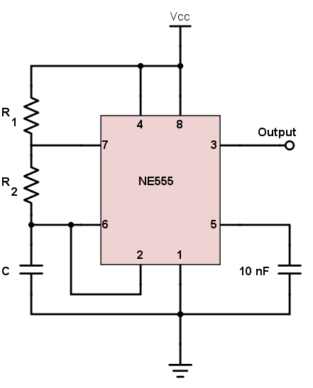
The 555 timer shown above is configured as an astable circuit. This means that the output voltage is a periodic pulse that alternates between the VCC value and 0 volts.

How to Calculate Output Voltage Frequency
The frequency is the number of pulses per second. The formula to calculate the frequency of the output voltage is:
$$f = \frac{1.44}{(R_{1}+2R_{2})C}$$
The period is the time covered for one pulse. This is just the reciprocal of the frequency:
$$T = \frac{1}{f} = 0.694(R_{1}+2R_{2})C$$
The high time ($$T_{1}$$) and low time ($$T_{0}$$) can be calculated using the formulas below. Note that the period is the sum of the high time and the low time.
$$T_{1} = 0.694(R_{1}+R_{2})C$$
$$T_{0} = 0.694R_{2}C$$
The mark space ratio is the ratio between the high time and the low time or:
$$\text{Mark Space Ratio} = \frac{T_{1}}{T_{0}}$$
The duty cycle is more commonly used than the mark space ratio. The formula for the duty cycle is:
$$\text{Duty Cycle} = \frac{T_{1}}{T} \text{ x } 100$$
A 50% duty cycle means the high time is equal to the low time. If an LED is placed at the output of this astable circuit, it will turn on at the same span of time as it is turned off. Note that getting an exact 50% duty cycle is impossible with this circuit.
Notes
- Increase $$C$$ to increase the period (reduce the frequency).
- Increase $$R_{1}$$ to increase High Time ($$T_{1}$$), without affecting the Low Time ($$T_{0}$$).
- Increase $$R_{2}$$ to increase High Time ($$T_{1}$$), increase Low Time ($$T_{0}$$) and decrease the duty cycle.
Applications
Synchronous Circuit Timer
A synchronous circuit is a digital circuit in which the changes in the state of memory elements, commonly flip-flops, are synchronized by a clock signal. Because of their availability and ease of use, the 555 astable circuit is the common source of clock signal in many synchronous circuits. A shift register--an example of a synchronous circuit--is shown below. Normally you would connect the output of the 555 astable circuit to the clock pin of this shift register.
LED Flasher
Although you can build a simpler LED flasher using a single transistor, some resistors, and a capacitor, most people would rather use a 555 astable circuit. See circuit below:

How fast would the LED blink? Of course, you can use our calculator to find that out.
Tone Generator
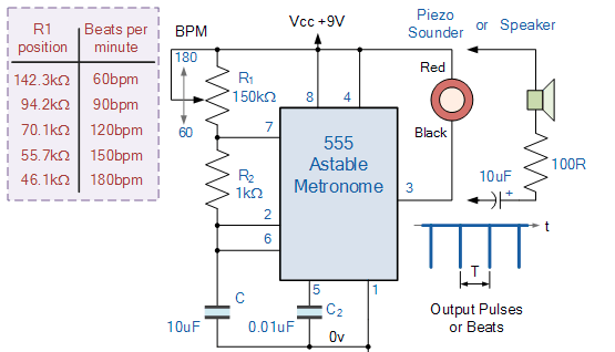
The circuit above produces an audible tone and is just one of the many sound-generating circuits that employ the 555 astable circuits. A 150kΩ potentiometer is used to adjust the frequency of the tone. It is possible to preset the output's upper and lower limits to predefined values by adding resistors or trimmers in series with the potentiometer.


Hello,
I was doing some calculations on the 555 Timer Astable Circuit Calculator page.
https://www.allaboutcircuits.com/tools/555-timer-astable-circuit/
But I am thinking that the results are incorrect. Mainly the Time High (T1).
I entered C as 100uF, R1 as 4.7M and R2 as 1k.
Time High (T1) shows as 326.4 millisecs(ms) but I think this should be 326.4 seconds