Edge Coupled Trace Inductance Calculator
This calculator helps you compute for the inductance of an edge coupled trace.
Inputs
Output
Overview
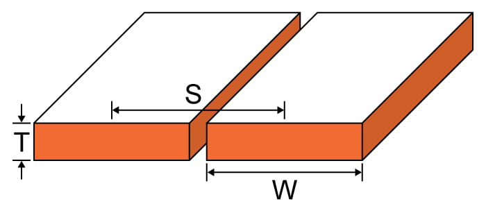
Traces in printed circuit boards can often form broadside or edge pairs and may introduce unwanted inductance. This tool is designed to calculate the inductance introduced by an edge-coupled trace. To use this calculator, enter the width of the trace, its separation (measured from the center), the thickness of the trace, and the relative permeability (which is usually 1, as air is the most common medium).
Equation
$$L_{coplanar}\approx \frac{\mu _{o}\mu _{r}}{\pi}\cosh^{-1}\left ( \frac{S}{W} \right )$$ $$\left ( d >> w, w > t \right )$$
Where:
$$S$$ = trace separation
$$T$$ = trace thickness
$$W$$ = trace width
$$\mu_{r}$$ = relative permeability
$$\mu_{0}$$ = permeability of free space = 4π x 10-7
Applications
A circuit's overall performance can be affected by a simple inductance between two traces (either broadside or edge-coupled) in a circuit board. For this reason, engineers must consider such inductance as part of their design plans. Board manufacturers are forced to used higher density routing of signal traces because of the rising cost in production. Higher density routing results in increased crosstalk between traces, and so their inductance has become a necessary design parameter.