The goal of series-parallel resistor circuit analysis is to be able to determine all voltage drops, currents, and power dissipations in a circuit. The general strategy to accomplish this goal is as follows:
This may sound like an intimidating process, but its much easier understood through example than through description.
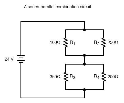
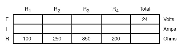
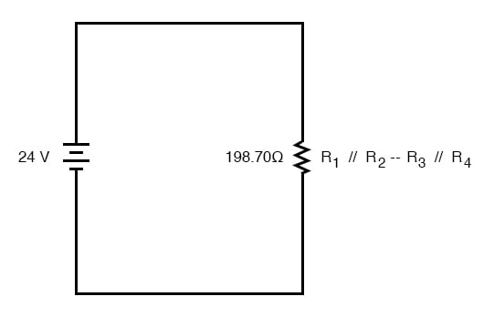
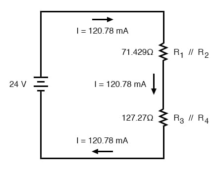
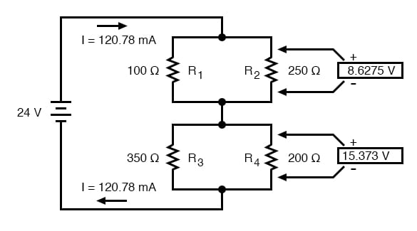
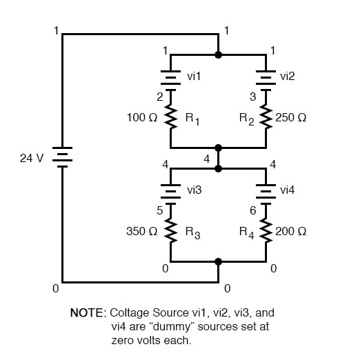
In the example circuit above, R1 and R2 are connected in a simple parallel arrangement, as are R3 and R4. Having been identified, these sections need to be converted into equivalent single resistors, and the circuit re-drawn:
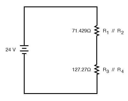
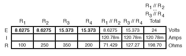
The double slash (//) symbols represent “parallel” to show that the equivalent resistor values were calculated using the 1/(1/R) formula. The 71.429 Ω resistor at the top of the circuit is the equivalent of R1 and R2 in parallel with each other. The 127.27 Ω resistor at the bottom is the equivalent of R3 and R4 in parallel with each other.
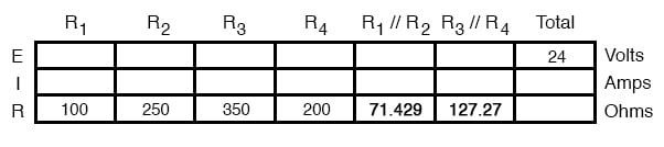
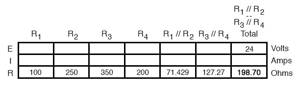
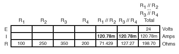
Our table can be expanded to include these resistor equivalents in their own columns:
It should be apparent now that the circuit has been reduced to a simple series configuration with only two (equivalent) resistances. The final step in reduction is to add these two resistances to come up with a total circuit resistance. When we add those two equivalent resistances, we get a resistance of 198.70 Ω.
Now, we can redraw the circuit as a single equivalent resistance and add the total resistance figure to the rightmost column of our table. Note that the “Total” column has been relabeled (R1//R2—R3//R4) to indicate how it relates electrically to the other columns of figures. The “—” symbol is used here to represent “series,” just as the “//” symbol is used to represent “parallel.”
Now, total circuit current can be determined by applying Ohm’s Law (I=E/R) to the “Total” column in the table:
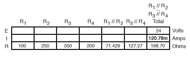
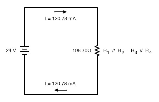
Back to our equivalent circuit drawing, our total current value of 120.78 milliamps is shown as the only current here:
Now we start to work backwards in our progression of circuit re-drawings to the original configuration. The next step is to go to the circuit where R1//R2 and R3//R4 are in series:
Since R1//R2 and R3//R4 are in series with each other, the current through those two sets of equivalent resistances must be the same. Furthermore, the current through them must be the same as the total current, so we can fill in our table with the appropriate current values, simply copying the current figure from the Total column to the R1//R2 and R3//R4 columns:
Now, knowing the current through the equivalent resistors R1//R2 and R3//R4, we can apply Ohm’s Law (E=IR) to the two right vertical columns to find voltage drops across them:
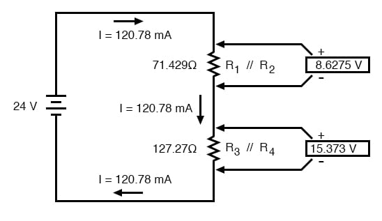
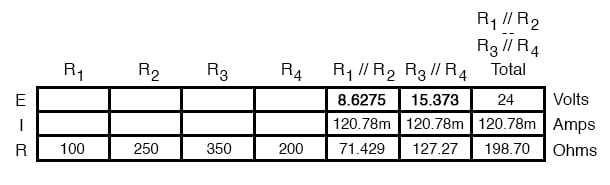
Because we know R1//R2 and R3//R4 are parallel resistor equivalents, and we know that voltage drops in parallel circuits are the same, we can transfer the respective voltage drops to the appropriate columns on the table for those individual resistors. In other words, we take another step backwards in our drawing sequence to the original configuration, and complete the table accordingly:
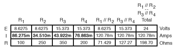
Finally, the original section of the table (columns R1 through R4) is complete with enough values to finish. Applying Ohm’s Law to the remaining vertical columns (I=E/R), we can determine the currents through R1, R2, R3, and R4 individually:
Having found all voltage and current values for this circuit, we can show those values in the schematic diagram as such:
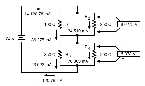
As a final check of our work, we can see if the calculated current values add up as they should to the total. Since R1 and R2 are in parallel, their combined currents should add up to the total of 120.78 mA. Likewise, since R3 and R4 are in parallel, their combined currents should also add up to the total of 120.78 mA. You can check for yourself to verify that these figures do add up as expected.
A computer simulation can also be used to verify the accuracy of these figures. The following SPICE analysis will show all resistor voltages and currents (note the current-sensing vi1, vi2, . . . “dummy” voltage sources in series with each resistor in the netlist, necessary for the SPICE computer program to track current through each path). These voltage sources will be set to have values of zero volts each so they will not affect the circuit in any way.
series-parallel circuit
 v1 1 0
 vi1 1 2 dc 0
 vi2 1 3 dc 0
 r1 2 4 100
 r2 3 4 250
 vi3 4 5 dc 0
 vi4 4 6 dc 0
 r3 5 0 350
 r4 6 0 200
 .dc v1 24 24 1
 .print dc v(2,4) v(3,4) v(5,0) v(6,0)
 .print dc i(vi1) i(vi2) i(vi3) i(vi4)
 .end
I’ve annotated SPICE’s output figures to make them more readable, denoting which voltage and current figures belong to which resistors.
| v1 | v(2,4) | v(3,4) | v(5) | v(6) |
|---|---|---|---|---|
| 2.40E+01 | 8.63E+00 | 8.63E+00 | 1.54E+01 | 1.54E+01 |
| Battery voltage | R1 voltage | R2 voltage | R3 voltage | R4 voltage |
| v1 | i(vi1) | i(vi2) | i(vi3) | i(vi4) |
|---|---|---|---|---|
| 2.40E+01 | 8.63E-02 | 3.54EE-02 | 4.39E-02 | 7.69E-02 |
| Battery voltage | R1 current | R2 current | R3 current | R4 current |
As you can see, all the figures do agree with the calculated values.
REVIEW:
RELATED WORKSHEETS:

In Partnership with Future Electronics

by Jake Hertz


by Duane Benson


