A wound rotor induction motor has a stator like a squirrel cage induction motor, but a rotor with insulated windings brought out via slip rings and brushes.
However, no power is applied to the slip rings. Their sole purpose is to allow resistance to be placed in series with the rotor windings while starting (figure below). This resistance is shorted out once the motor is started to make the rotor look electrically like the squirrel cage counterpart.
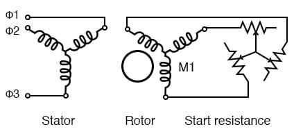
Wound rotor induction motor
Q: Why put resistance in series with the rotor?
A: Squirrel cage induction motors draw 500% to over 1000% of full load current (FLC) during starting. While this is not a severe problem for small motors, it is for large (10’s of kW) motors.
Placing resistance in series with the rotor windings not only decreases start current, locked rotor current (LRC) but also increases the starting torque, locked rotor torque (LRT). The figure below shows that by increasing the rotor resistance from R0 to R1 to R2, the breakdown torque peak is shifted left to zero speed.
Note that this torque peak is much higher than the starting torque available with no rotor resistance (R0) slip is proportional to rotor resistance, and pullout torque is proportional to slip. Thus, high torque is produced while starting.
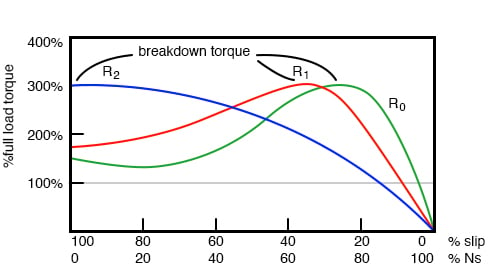
Breakdown torque peak is shifted to zero speed by increasing rotor resistance
The resistance decreases the torque available at full running speed. But that resistance is shorted out by the time the rotor is started. A shorted rotor operates like a squirrel cage rotor. The heat generated during starting is mostly dissipated external to the motor in the starting resistance.
The complication and maintenance associated with brushes and slip rings is a disadvantage of the wound rotor as compared to the simple squirrel cage rotor.
This motor is suited for starting highly inertial loads. A high starting resistance makes the high pull out torque available at zero speed. For comparison, a squirrel cage rotor only exhibits pull out (peak) torque at 80% of its synchronous speed.
Motor speed may be varied by putting variable resistance back into the rotor circuit. This reduces the rotor current and speed. The high starting torque available at zero speed, the downshifted break down torque, is not available at high speed.
See R2 curve at 90% Ns, the figure below. Resistors R0, R1, R2, R3 increase in value from zero.
A higher resistance at R3 reduces the speed further. The speed regulation is poor with respect to changing torque loads. This speed control technique is only useful over a range of 50% to 100% of full speed.
Speed control works well with variable speed loads like elevators and printing presses.

Rotor resistance controls the speed of wound rotor induction motor
We previously described a squirrel cage induction motor acting as a generator if driven faster than the synchronous speed. (See Induction motor alternator) This is a singly-fed induction generator, having electrical connections only to the stator windings.
A wound rotor induction motor may also act as a generator when driven above the synchronous speed. Since there are connections to both the stator and rotor, such a machine is known as a doubly-fed induction generator (DFIG).

Rotor resistance allows over-speed of doubly-fed induction generator
The singly-fed induction generator only had a usable slip range of 1% when driven by troublesome wind torque. Since the speed of a wound rotor induction motor may be controlled over a range of 50-100% by inserting resistance in the rotor, we may expect the same of the doubly-fed induction generator.
Not only can we slow the rotor by 50%, but we can also over speed it by 50%. That is, we can vary the speed of a doubly-fed induction generator by ±50% from the synchronous speed. In actual practice, ±30% is more practical.
If the generator over-speeds, resistance placed in the rotor circuit will absorb excess energy while the stator feeds constant 60 Hz to the power line (figure above). In the case of under-speed, negative resistance inserted into the rotor circuit can make up the energy deficit, still allowing the stator to feed the power line with 60 Hz power.

Converter recovers energy from the rotor of the doubly-fed induction generator
In actual practice, the rotor resistance may be replaced by a converter absorbing power from the rotor, and feeding power into the power line instead of dissipating it. This improves the efficiency of the generator.

Converter borrows energy from the power line for the rotor of the doubly-fed induction generator, allowing it to function well under the synchronous speed
The converter may “borrow” power from the line for the under-speed rotor, which passes it on to the stator. The borrowed power, along with the larger shaft energy, passes to the stator which is connected to the power line.
The stator appears to be supplying 130% of power to the line. Keep in mind that the rotor “borrows” 30%, leaving the line with 100% for the theoretical lossless DFIG.
RELATED WORKSHEET:

In Partnership with Future Electronics

by Jake Hertz


by Jake Hertz

