
A New Non-Contact Current Sensor IC from ROHM Semiconductor
This high-sensitivity device is designed for space-constrained and low-power applications.
This high-sensitivity device is designed for space-constrained and low-power applications.
As you surely know, measuring current is a perpetually problematic design task. Measuring voltage is so easy by comparison that it’s hard to not be a little bit biased against current. Come on, current—why can’t you be more like voltage? We just want to know your amplitude without disturbing the rest of the circuit!
The most straightforward way to measure current is to place a known resistance in series with the current path. You simply measure the voltage across the known resistance and apply Ohm’s law. This resistive method of measurement is often effective, though it can’t be used when the additional resistance would negatively affect the operation of the circuit.
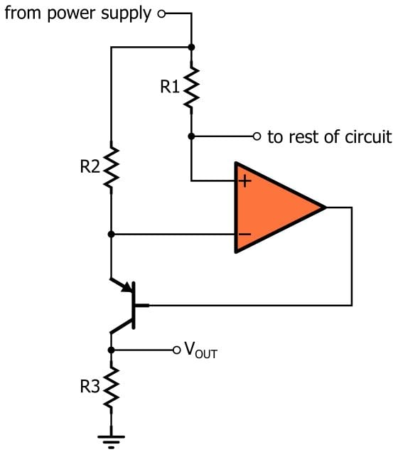
This is a more elaborate way to use resistance for measuring current. The circuit is discussed in this article from AAC’s Analog Circuit Collection.
Nonintrusive versions of current sensing are based on the fact that current flowing through a conductor generates a magnetic field. The article mentioned in the previous paragraph also discusses Hall effect sensors, which can produce an output voltage that is proportional to current without introducing a significant amount of resistance into the current path.
Concerns with Hall Effect Sensors
Hall effect sensors are by no means an ideal solution, though, and ROHM Semiconductor has recently announced an IC that they perceive as far superior to typical magnetic-field-based current-sensing devices.
According to ROHM, integrated-circuit Hall effect sensors occupy too much board space and dissipate too much power. Furthermore, they must compensate for their low sensitivity by drawing current within the sensor itself, which means that these sensors are not as nonintrusive as they seem. Indeed, ROHM does not consider a typical IC Hall effect sensor to be a truly contactless device—i.e., a device that measures current without introducing any loss.
The Magneto-Impedance Approach
The folks at ROHM believe that they have overcome the limitations of Hall effect sensors by building a current-sensing device around a magneto-impedance element. If you don’t know what a magneto-impedance element is, don’t worry— I had never even seen this term until I started writing this article.
I did a bit of research, and my understanding is as follows: The behavior of a magneto-impedance element is based on the magneto-impedance (MI) effect. The MI effect is a phenomenon whereby an external magnetic field applied to an amorphous magnetic wire affects the voltage generated in this wire by a high-frequency current source. This allows an MI element to be used as the basis for a highly responsive and highly sensitive magnetic field sensor.
ROHM’s Magneto-Impedance Current Sensor
The following block diagram gives you a general idea of what’s inside the BM14270MUV-LB contactless current sensor from ROHM.

Block diagram of the BM14270MUV-LB from the datasheet.
As you can see, it’s much more than just a sensor. It also provides analog and digital signal processing, analog-to-digital conversion, and I2C communication for delivering the current-sensing data to a microcontroller. In other words, it’s a highly integrated device that packs a lot of functionality into a small (3.5 mm × 3.5 mm) package. In fact, ROHM describes it as the “industry’s smallest” non-contact current sensor.
The information in the datasheet could be a bit more clear, but I think that I understand how this part is supposed to be used. The idea is that the IC is soldered to the top (or bottom) of the board and it measures the current flowing through a trace located in an internal layer such that the trace is directly beneath the sensor.

Diagrams showing current flow through the sensor. Image from the datasheet.
ROHM describes this as “completely contactless current detection,” because the current does not even need to flow through the device. It just flows underneath it.
Noise Cancellation
The boxes labeled A and B in the side-view diagram are two magneto-impedance sensors pointing in opposite directions. The output is generated by subtracting the B measurement from the A measurement. This doesn’t cancel out the overall measurement, because each sensor is exposed to current flowing in a different direction. However, it does cancel the effect of external magnetic fields, because these fields will be the same for both sensors.

From the BM14270MUV-LB press release.
ROHM refers to this feature as “disturbance magnetic field cancellation.” It seems to me like a very good idea and ROHM indicates that an unshielded BM14270MUV is as robust against external magnetic fields as a typical Hall effect sensor that includes a mechanical shield.
This new magneto-impedance sensor from ROHM seems like a fairly impressive device. However, do you think that their criticism of Hall effect sensors is a bit exaggerated? Have you ever found Hall effect sensing to be problematic enough to make you search for an alternative solution? Feel free to share your thoughts in the comments section below.


Awesome! Funny thing is, as I was reading the article, just because where you have the diagram of the traces, I imaged that would be the way the sensing would work. Though, I was thinking only 1 trace, not a twin U trace. I think my understanding of electronics is started to make sense