
Track Overhead Flights with a Raspberry Pi Zero Wireless, a Software Defined Radio, and FlightAware
This article shows you two ways to use a Raspberry Pi Zero Wireless to track flights in your area. It also demonstrates how it can control a 64×64 RGB matrix.
The Raspberry Pi Zero Wireless is a $10 microcomputer capable of a great many things. This article shows you two ways to use this Pi to track flights in your area. It also demonstrates how it can control a 64×64 RGB matrix to display flight numbers!
In this article, I'll do three separate projects using the Raspberry Pi Zero Wireless. In Project 1, I'll create a plane-tracking device using PiAware. In Project 2, I'll collect data from said planes. In Project 3, I'll show you how to use the RPi Zero W to control a 64×64 RGB matrix.
Project 1: Raspberry Pi Zero Wireless Plane Tracker
| Part | Cost | Notes |
|---|---|---|
| Raspberry Pi Zero Wireless | $10 | |
| SDR receiver | $21 | Many other USB SDR receivers will likely work |
| 4GB microSD card | $6 | Larger cards will work |
| USB-to-MicroUSB adapter | $5 | |
| MicroUSB Hub (optional) | $8 | The Pi Zero only has microUSB ports; to attach accessories, you need a hub/converter |
| Wideband antenna (optional) | $50 | Antenna must cover 1090 MHz |
| 1090 MHz band-pass filter (optional) | $20 |
Resources
This experiment was done using the Raspberry Pi Zero Wireless. However, the following code should work on any Raspberry Pi version 2 or later. If you purchase a Pi Zero without wireless, you can add it with a wireless USB network dongle.
Step 1: Prepare the SD card
Download the latest Raspbian Jessie to your computer.
Write the image to your SD card (here are guides for Linux, Mac OS, and Windows).
Step 2: Modify the SD card
Create a file named "ssh" in the root directory of the SD card. No file extension, no file contents. This file enables SSH, which will allow you to remotely access the Pi.
Create a file named "wpa_supplicant.conf" with the following contents. Change the values for YourWifiName and YourWifiPassword to the name and password you use to connect to your Wi-Fi network.
ssid="YourWifiName"
psk="YourWifiPassword"
key_mgmt=WPA-PSK
}
Step 3: Install and Boot
Eject the SD card from your computer and install it in the Raspberry Pi Zero Wireless. Connect the Raspberry Pi to a power source using the MicroUSB port closest to the end of the board. Wait approximately one minute for the Raspberry Pi to boot and connect to Wi-Fi. With these configuration files, there is no need to use a keyboard, mouse, or display with your device.
Step 4: Locate Your Pi
Identify the IP address of your Pi—this can be accomplished by logging into your router and looking at attached devices, or through an IP scanner such as Look@Lan (Windows) or nmap (Linux and Mac). If your device does not appear within two or three minutes, disconnect power, remove the SD card from the Pi, and reinsert it in your computer and double-check the ssh and wpa_supplicant.conf files.
Step 5: Connect to Your Pi
Windows: Use a tool such as Putty to connect to your Pi. Download and run the program, type the IP address of your Pi, and click "connect". A window will appear that asks you about the security certificate—click "yes".
Linux and Mac: Open a terminal and type "ssh pi@raspberrypi.local" or "ssh pi@ipaddress" (e.g., "ssh pi@192.168.0.52").
At the prompt, the default username is "pi" and the default password is "raspberry".
Step 6: Configure Your Pi
Type "sudo raspi-config" and hit enter.
Change your password, timezone, and localization.
When the password prompt appears, the current password is "raspberry"; you should change it to something more secure to make it at least marginally difficult to hack your device. On a side note, instead of passwords, you should use certificates for authentication, but that will not be discussed in this article.
Then type the following commands and allow them to run:
sudo dpkg -i piaware-repository_3.3.0_all.deb
sudo apt-get update
sudo apt-get dist-upgrade -y
sudo apt-get install -y piaware fail2ban libio-socket-ssl-perl
sudo piaware-config allow-auto-updates yes
sudo piaware-config allow-manual-updates yes
sudo apt-get install dump1090-fa -y
sudo reboot
After the Rapsberry Pi has finished the boot process, open a web-browser on your computer and navigate to http://raspberrypi.local:8080 (or replace raspberrypi.local with the IP address of your device). Zoom out and then zoom into your location as planes begin to appear and then disappear from your screen.
To increase the number of planes, take your Pi, SDR, and antenna system outside. Further improvements are found by adding the 1090 MHz band-pass filter and a better antenna.
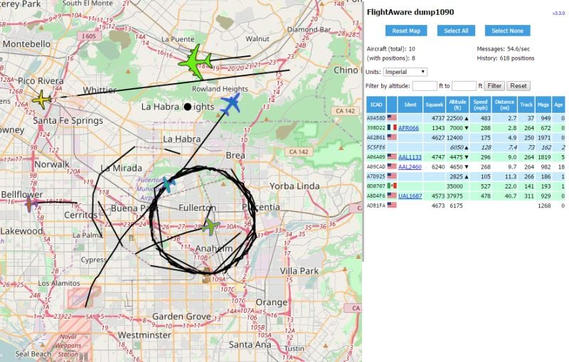
Screenshot of PiAware receiver that shows an area east of Los Angeles, California, on 3/14/17 (Pi Day!). Linear tracks at the top show planes ready to land at LAX. Also visible is a government plane flying in circles.
Finally, create a FlightAware.com account and then associate your receiver with your FlightAware.com account.
ADS-B, PiAware, and dump1090
Transponders affixed to aircraft allow them to broadcast a four-digit octal identifier (Mode-A AKA "Squawk") identifier plus altitude (Mode-C), a 24-bit unique ICAO number (Mode-S), and the 24-bit ICAO number with additional information (Mode S Extended Squitter). The last mode is also known as ADS-B.
Automatic Dependent Surveillance-Broadcast (ADS-B) takes an aircraft's position (as determined by GPS, GLONASS, etc.), combines it with identifying information, and broadcasts it at 1090 MHz. Unlike the other transponder codes, which are only transmitted as a reply to an interrogation by a radar signal, ADS-B is transmitted approximately twice per second.
PiAware and dump1090 use a Software Defined Radio (SDR) tuned to 1090 MHz to receive and decode the broadcasts of all aircraft in the vicinity and send them to FlightAware's servers. The information is displayed on a web page hosted on the Raspberry Pi at port 8080.

Illustration by John Macneil, www.aopa.org.
All aircraft must be equipped with ADS-B Out transponders by January 1, 2020. But, until then, FlightAware uses multilateration to determine the location of planes that do not broadcast their latitude and longitude. Multilateration uses the known position of at least three receivers and the times of reception of a message to calculate the position of a plane.
Project 2: Using the Pi Zero Wireless to Collect Plane Data from FlightAware.com
FlightAware.com has two Application Program Interfaces (API) that allow data to be mined and utilized: FlightXML and Firehose. Choose between the two based on the type of information that you need and how many queries you need each month. For this project, All About Circuits was granted free access for one month. To follow along, you will need to contact FlightAware.com for an API key.
Resources:
Step 1: Test Connectivity
Connect to your Pi Zero over SSH and test connectivity to the Firehose API.
If you see a page or two of certification details, everything worked correctly.
Step 2: Get Sample Files and Data
FlightAware hosts sample files in GitHub. Begin by downloading and editing the sample files with your username and API key.
cd firehose_examples/perl/example1
sudo nano example1.pl
Change the username and apikey fields to match your information, then exit ([Ctrl]+[x]) and save.
You should see data in JavaScript Object Notation (JSON) format:
$VAR1 = {
'aircrafttype' => 'B738',
'heading' => '105',
'pitr' => '1490038420',
'gs' => '334',
'clock' => '1490038413',
....
'hexid' => 'A44591',
'ident' => 'DAL751'
'alt' => '25100',
'lon' => '-117.38051',
'lat' => '33.53288'
};
Step 3: Configure Your Pi to Collect Data
Firehose is aptly named in that it can produce an overwhelming amount of data in a very short period of time (~1 GB/day)—filling your disk and increasing the charges to your account. So when you create a script to gather information, you should check it at regular intervals as you could very quickly fill your disk and empty your expense account.
Depending on the size of your MicroSD card and what you hope to collect, you might need to add additional storage or go back to raspi-config and expand your filesystem (option 7, option A1).
For my example, I am going to collect data for a 2° × 2° geographic area that includes LGB, LAX, ONT, SNA, etc. (34° N ± 1°, 118° W ± 1°). I chose this region because it approximates my area of reception.

The area of interest ranges from 33° N to 35° N and 117° W to 119° W.
The following code is example1.pl, with changes to line 18 and 45. All lines are shown below so readers can follow along without having to download the file. Create a copy of example1.pl called position.pl and use nano to edit position.pl.
sudo nano position.pl
Make the necessary edits and exit with [Ctrl]+[x].
 1 #!/usr/local/bin/perl
 2
 3 use strict;
 4 use IO::Socket::SSL;
 5 use JSON::PP;
 6 use IO::Uncompress::Inflate qw($InflateError);
 7 use Data::Dumper;
 8
 9 my $username = 'allaboutcircuits';
10 my $apikey = 'allaboutcircuitsreallylongapikey';
11 my $compression = 0;
12
13 # Open the TLS socket connection to FlightAware.
14 my $sock = IO::Socket::SSL->new('firehose.flightaware.com:1501') or die $!;
15 # print "Connected!\n";
16
17 # Send the initiation command to the uncompressed socket.
18 my $initcmd = "live version 8.0 user $username password $apikey events \"position\" latlong \"33 -117 35 -119\"";
19 if ($compression) {
20     $initcmd .= " compression compress";
21 }
22 binmode $sock;
23 print $sock "$initcmd\n";
24
25 # Activate compression, if requested.
26 my $zsock;
27 if ($compression) {
28     $zsock = new IO::Uncompress::Inflate $sock
29         or die "IO::Uncompress::Inflate failed: $InflateError\n";
30 } else {
31     $zsock = $sock;
32 }
33
34 # Main loop, reading lines of JSON from the server.
35 my $i = 1;
36 while (my $line = $zsock->getline()) {
37     #print "LINE $i\n";
38     #print "LINE $i: ", $line, "\n";
39
40     my $data = eval { decode_json $line };
41     die "Failed to decode JSON: $line" if !defined($data) || $@;
42
43     print $data->{ident}."    \t".$data->{lat}." \t " . $data->{lon} . " \t". $data->{alt}." \n";
44
45     last if ($i++ >= 10);
46 }
47 close $sock;
48
49 # print "All done.\n";
Line 18 limits the request to planes in the geographic region between 117° W and 119° W (denoted by -117 and -119). Line 43 is modified to demonstrate a method to target just the fields of interest. In this case, we'll target a plane's flight number, latitude, longitude, and altitude. Line 45 requests 10 planes from the server (this line can be commented out in a final script).
The next two commands execute the program and allow you to monitor the program's progress:
tail -f position.txt
The first line has the superuser use the program perl to run the program position.pl and append (>>) the output to the file position.txt and the & symbol causes the program to run in the background.
The second line uses the program tail to follow (-f) changes to the file position.txt, which allows you to monitor the command for completion. When done, use [Ctrl]+[c] to exit tail. If you are no longer interested in collecting data, use fg to bring the program position.pl to the foreground and stop it or break it with [Ctrl]+[c].
The below .zip file contains modified programs and output that hopefully demonstrate how slight changes in the syntax can bring different information into focus, along with sample output from the programs.
- arrivals.pl gives JSON output for planes that have just touched down (either arriving or departing LAX)
- test_landing.pl gives readable output (e.g., AAL1155 landed at 03/21/2017 22:00:01)
- position.pl gives JSON output for all planes in the geographic rectangle (34° N ± 1°, 118° W ± 1°)
- test_overhead.pl gives flight identification, latitude, longitude, and altitude (N721PP 34.36011 -118.37837 18100)
These files were made with minor modifications to the example1.pl provided by FlightAware. To make your own that captures only the data that interests you, use the FlightAware Firehose API documentation to request the appropriate information in JSON format, and then use the correct syntax inside the file to only output the information you need.
Project 3: Using the Pi Zero Wireless to Control a 64×64 RGB Matrix
| Part | Cost | Notes |
|---|---|---|
| (2) 2× 32×32 RGB display matrix + power supply | $75 ($150) | Requires four total 32×32 RGB matrix to create 64×64 pixel display |
| Adafruit RGB matrix HAT + RTC clock | $25 | Datasheets |
| 20-pin IDC cable (Hub75) | $7-$13 | The length required depends on configuration of panels and distance to the Pi |
| 0.1" male headers (40-pin, 2×20) | $1 | 2.54 mm |
Step 1: Adafruit Matrix HAT Preparation
Solder the male and female headers on the Adafruit HAT according to the instructions at Adafruit.com. Then solder a wire or attach a jumper between pins 4 and 18. For this project, you do not need to attach either the DC barrel jack or the screw terminal connectors.
Step 2: Raspberry Pi Preparation
Solder the 2×20 male headers into place.
Step 3: RGB Matrix Preparation
Orient the RGB matrices so the arrows on the bottom row are pointed down and the arrows on the top row are pointed up (see image here). Use a 2×10 IDC cable to connect the output of the Adafruit HAT to the input of the first board. Then connect the output of the first board to the input of the second, the output of the second to the input of the third, etc.

The backside of the RGB matrix panel. The signal travels from board to board in a "C" shape.
If you are fortunate enough to have a laser cutter or CNC machine at your disposal, I have included the drawings for a back plate that can hold all four of the RGB matrix plates used. The mounting holes are replaced with slots to allow alignment from a common center point.

Template for mounting four 32×32 panels to make a large 64×64 panel; Various panel arrangements are possible.
Full Documentation and Source Code by Hennen Zeller.
Once all of the electrical connections have been made, power on the Raspberry Pi. After approximately one minute, attempt to log onto the Pi with Putty or SSH.
Once in, type the following to disable the sound on the Pi (documentation indicates a hardware subsystem conflict with sound and the RGB matrix hardware).
blacklist snd_bcm2835
EOF
sudo update-initramfs -u
Then use apt-get to install Python and imaging files.
Get the necessary files to run the RGB matrix and compile them.
cd rpi-rgb-led-matrix
HARDWARE_DESC=adafruit-hat-pwm make -C examples-api-use
sudo examples-api-use/demo -L -D0
cd utils/
HARDWARE_DESC=adafruit-hat-pwm make
Optionally, if you also have a camera connected to your Pi, you can capture a 64×64 pixel image and feed it to the display.
sudo ./led-image-viewer -L -f myimg.png
The previous two lines capture a 64×64 image to the display and use the program led-image-viewer (compiled in the previous section) to display it on the Large display (-L) forever (-f).
What Next?
You now have a $10 computer that can track (either with an antenna and SDR receiver or with an API call) aircraft around you and display any information about those that you want on your 64-pixel by 64-pixel display, or on the Raspberry Pi Zero W's HDMI output.
What you do with it is limited only by your imagination.
Since this article only introduces the tools, the first step I recommend is reading the documentation for the display and FlightAware and then opening the example programs of both to better understand their capabilities.
And don't forget that your Raspberry Pi Zero is a functioning Linux installation complete with often-used commands such as Cron, Grep, and Awk. Anything that is not already on your Pi is just a short apt-get install away.
Check out the video below to see the culmination of these projects!
Give this project a try for yourself! Get the BOM.


Readers—I was informed by the officers of FlightAware.com that FlightAware 3.5 came out today, and it has Pi Zero Wireless support, Which makes setting up a receiver that much easier. See https://discussions.flightaware.com/post196589.html for more details.
In case you (like me) are new here and think that 50% of this article is missing, you click on the PRICES to get more information on the components the author is using.