Ladder Logic in Programmable Logic Controllers (PLCs)
This article describes the programming language ladder logic used to program PLCs and shows examples of how it functions.
Ladder diagram, better known as ladder logic, is a programming language used to program PLCs (programmable logic controllers). This article will briefly describe what ladder logic is and go over some examples of how it functions.
Programmable logic controllers or PLCs are digital computers used to perform control functions, usually for industrial applications. Of the various languages one can use to program a PLC, ladder logic is the only one directly modeled after electromechanical relay systems.
It uses long rungs laid out between two vertical bars representing system power. Along the rungs are contacts and coils, modeled after the contacts and coils found on mechanical relays. The contacts act as inputs and often represent switches or push-buttons; the coils behave as outputs such as a light or a motor.
Outputs don't have to be physical, though, and can represent a single bit in the PLC's memory. This bit can then be used later on in the code as another input. Contacts are placed in series to represent AND logic and in parallel when using OR logic. As with real relays, there are normally open contacts and normally closed contacts.
An Example of Ladder Logic
Let’s take a look at an example of ladder logic programming:
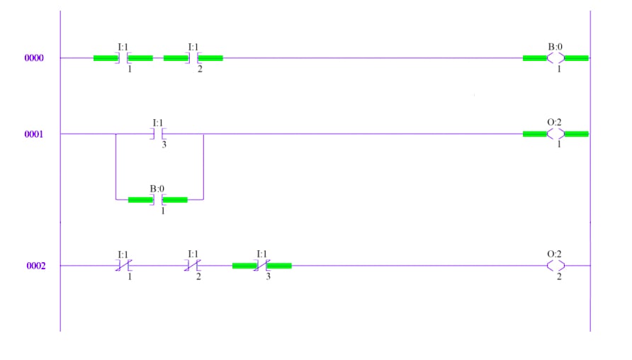
Figure 1. A simple ladder logic program
This ladder logic program is three rungs long. The program is “scanned” or run by the CPU from left to right and top to bottom. The symbols placed throughout the rungs are actually graphical instructions. The names for these instructions are:
- XIC (Examine If Closed)
- XIO (Examine If Open)
- OTE (Output Energize).
First Rung
Looking at the first rung, notice the first two inputs I:1/1 and I:1/2. The symbol is an XIC, and the I denotes that this is an input. This instruction represents a physical input found on one of the discrete input cards.
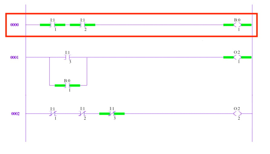
Figure 2. The first rung represents a physical input found on one of the discrete input cards.
I:1 means that this input card has been placed in slot 1, directly adjacent to the processor. The /1 indicates the bit of interest. Input cards have more than one channel, and if the instruction specifies /1, the instruction accesses channel 1.
The second input represents channel 2 on the same card. An XIC instruction really means true if closed. That is, this instruction will be true if the input device it represents is closed. If an instruction is true it is highlighted in green. The only way for an output to be energized is if a path of true instructions can be traced from the left rail to the right rail. Therefore, the output on rung one will be true because a path of true instructions, I:1/1 and I:1/2, exists. This is effectively an AND operation.
The output in this case, B:0/1, is actually an internal bit stored in the PLC's memory. That’s why it’s labeled B instead of O for “output.” These internal bits work great when a certain state or set of inputs needs to be recorded without actually turning on a physical output.
Second Rung
On the second rung, we have a third input labeled I:1/3 and our internal bit is now used with an input instruction instead of an output.
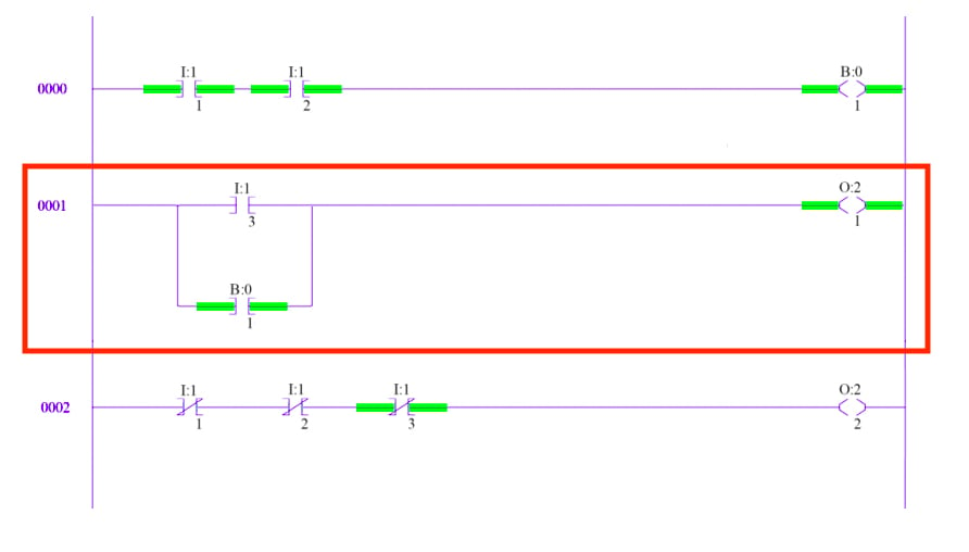
Figure 3. The second rung represents a third input used with an input instruction.
These two inputs are placed in parallel and represent an OR condition. O:2/1 is an output instruction that represents channel 1 on a physical discrete output card placed in slot 2. This second rung could be rewritten without the internal bit by replacing B:0/1 with the two inputs from rung one. Thus, output O:2/1 will be true if I:1/3 is true OR if both I:1/1 AND I:1/2 are true. This is the basic structure of all ladder logic programs.
Third Rung
The third rung introduces the XIO instruction. An XIO instruction is best described as true if open.
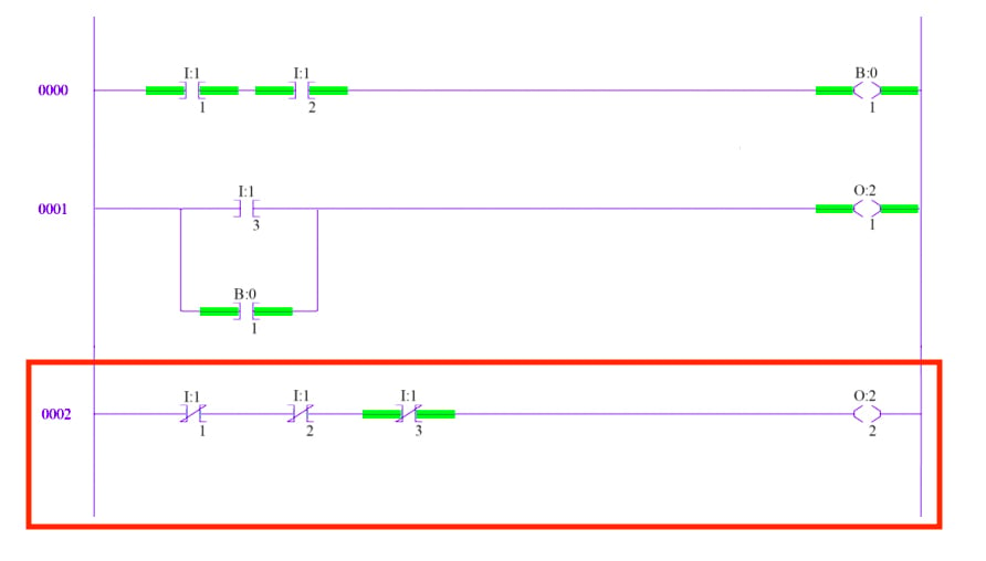
Figure 4. The third rung introduces the XIO instruction.
The XIO will be true only if the input connected to it is open. In the case of internal bits, this instruction is true if the internal bit is off. Therefore, because I:1/1 and I:1/2 are both closed, the XIO instructions representing those inputs are false. The XIO representing I:1/3 is true because the input device it represents is open. Without a path of true instructions from left to right, the output on rung three, O:2/2, is off.
PLC System Instructions
The instructions discussed above are the most fundamental instructions in PLC systems, but they represent a small portion of the entire instruction set. The majority of PLCs include timer, counter, latching, and advanced logic instructions.
Figure 5 shows a slightly more complicated level-control program written by the author for an Allen-Bradley PLC.
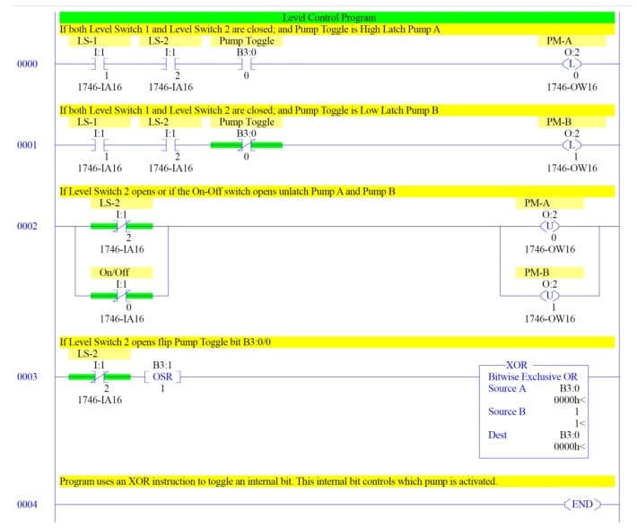
Figure 5. Level-control program
For starters, you might notice the input I:1/0. Confusingly, Allen-Bradley names the first channel on any card channel 0. This is similar to the way array indices start at zero.
This program uses two level switches, attached to a tank, to activate two pumps that must begin operation one after the other rather than simultaneously. Notice the same two XIC inputs control both pump A and B. However, an internal bit is used with an XIC to control pump A and with an XIO to control pump B. If rung 0000 is true, pump A gets latched using a latch instruction.
If rung 0001 is true, pump B gets latched. Once a latch instruction goes true, the output remains on until a complementary unlatch instruction is activated. The last rung controls the pump toggle, using a one-shot and an XOR instruction.
The one-shot, when activated, stays true for a single program scan, while the XOR behaves as usual. This is an easy way to toggle a bit with a single input.
The instructions used here are still only a fraction of what's available. Ladder logic can be used to build state machines, manipulate analog values, and even perform PID control.
For a more in-depth look at ladder logic, check out chapter 6 of volume IV of the AAC textbook, dedicated to ladder logic history, digital logic functions, and ladder logic applications.