
What Is Brown Out Reset in Microcontrollers? How to Prevent False Power-Downs
Brown Out Reset is an important function to increase the reliability of a microcontroller after start-up. Normally used to solve problems with the power supply, this article shows how Brown Out Reset can prevent another problem.
Review of Brown Out Reset
A “brown out” of a microcontroller is a partial and temporary reduction in the power supply voltage below the level required for reliable operation. Many microcontrollers have a protection circuit which detects when the supply voltage goes below this level and puts the device into a reset state to ensure proper startup when power returns. This action is called a “Brown Out Reset” or BOR. A similar feature is called Low Voltage Detect (LVD) which is more complex and adds detection of multiple voltage levels and can produce an interrupt before a reset is triggered.
BOR is often enabled by a bit in a control register. Typically, a status bit is set when the BOR causes a reset. This status bit survives the reset (if the power does not go too low!) and allows the program to detect the issue and perform additional recovery or log the event.
What happens if the BOR is disabled? Here is a depiction of a steadily dropping power supply voltage. Perhaps this is a deteriorating power supply or a discharging battery.

V1 is the normal power supply voltage. V2 is the point where the microcontroller may not operate reliably. I show V3 as a point where operation stops entirely. Between V2 and V3 is a “danger zone” where things can go wrong and operation is unreliable. The device could work correctly for years while the power supply goes in and out of the danger zone and then, bam!, there is a failure. The BOR level is set above V2 and replaces the danger zone with a reset of the device. Reset is not good but (usually) better than uncertain.
Next, I relate a situation where the power supply operated normally but BOR was used to solve a different problem.
Finding Another Use For Brown Out Reset (The Hard Way)
I designed a circuit containing a PIC microcontroller and 18 voltage regulators in a module controlling +5V power to 18 light sensors. Twelve modules controlled the 204 sensors in an array. The modules are part of an Adaptive Optics system at a large, astronomical telescope on Mauna Kea in Hawaii. Here is the inside of a module.

Pictures courtesy of the Subaru Telescope
The microcontroller is near the center of the board and the 18 linear voltage regulators are mounted to the walls of the enclosure. The modules and sensors are mounted on water cooled plates to move heat away from the optical bench which is over the sensor array. Pulses from the light sensors go into the module where they are converted to differential, RS-485 signals and output on the connector in the upper middle of the picture. In addition, there are RS-485 control signals which go into the module. All the RS-485 signals connect to circuits in a chassis about 10 meters away. An important point is all the circuitry in a module runs off the same +5V supply.
Here is a closeup of the microcontroller and RS-485 line drivers and receivers which are central to the problem. The black, modular jack is an asynchronous, serial interface which adds two more RS-485 I/O signals.

The modules went through extensive testing on the bench. No problems! They went through months of system testing in the laboratory. Perfect! The big event was the first testing at the telescope. Fail! Communication was lost to about half of the modules when the power was turned off and back on. I plugged in the debugger and found the microcontroller running and executing code but there were corrupted variables and the serial interface was not working. Very strange.
First, I want to say debugging in the middle of the night at an altitude of 13,589 feet (4,138 meters) with an air temperature of 40°F (4°C) is not fun. However, let’s move on. Here is a diagram showing the problem.
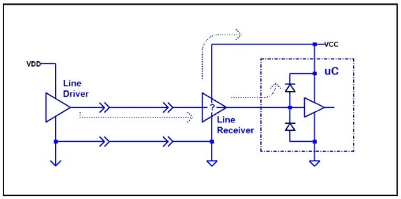
On the right side is the module with RS-485 line receivers connected to the microcontroller and the +5V supply. On the left side are line drivers at the other end of the cable which are always powered on. Actually, there are drivers and receivers going in both directions but I am simplifying. When the module power (VCC) was off, the remote line drivers and receivers were still on (VDD). The signals acted like power sources and found their way through the module interface devices and directly to the +5V power or through the ESD protection circuitry on the microcontroller pins. There was enough power to keep the microcontroller from powering down completely and the device was in the danger zone.
When the module power turned on, the microcontroller did not start with a normal power-on reset sequence. It started running but with problems. Why did this not show up during previous tests? Remember the water cooled plates? The coolant at the telescope was quite a bit colder than the coolant in the lab. My theory is the lower temperature was just enough to expose the problem in some of the modules.
The fix was easy. I added a statement in the code to enable BOR and the problem was solved. By the way, it took me much longer to write the report and convince the project manager everything was fine than it took to fix the problem.
False Power-Down
Here is a diagram showing the general problem.
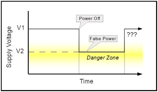
When the power supply is turned off the voltage does not go all the way down. Instead, other power sources keep the supply voltage in the danger zone. One description of this voltage is “False Power”. There is no BOR to detect this condition and cause a reset. The device may not go through the normal power-up sequence when the power is turned on again because the power-on reset circuitry may not be triggered. Subsequent operation is uncertain because the power supply went below the minimum and there is no reset.
In my case, the microcontroller was a Microchip PIC16F877-20I/L. This part is the industrial version with an operating temperature range of -40°C to +85°C. With a 16MHz clock, the power supply range is +4.0V to +5.5V. The operating voltage inside the module (V1) was a rock solid +5V. The False Power voltage at the microcontroller (V2) was about +1.5V when operating at the telescope. I did not measure it in the lab because there was no problem and I did not know to check for it. Furthermore, I never had a chance to check it with lab conditions because the system never came down from the telescope.
There are two other relevant specifications. The “RAM Data Retention Voltage” (\[V_{DR}\]) is +1.5V, “typical”. The “VDD Start Voltage” (\[V_{POR}\]) to insure an internal power-on reset is 0V, “typical”. Folding all this together tells me the device was well within the danger zone. No power-on reset could be expected because the voltage was well above \[V_{POR}\]. Also, there was no expectation that the False Power would keep the device alive since False Power was at the RAM retention voltage (\[V_{DR}\]). Who knows what the rest of the device was doing?
Why did turning on BOR fix the problem? The Brown Out Reset trigger specification (\[V_{BOR}\]) is a range from +3.7V to +4.35V with typical of +4.0V. The False Power level is well below the trigger voltage for BOR. Problem solved. However, there is still the mystery of why the microcontrollers worked in the lab and operated normally with many, many power cycles.
Conclusion
I found a description of this situation at the end of a Microchip application note (AN607) which calls it a “False Power-Down”. I have not found it documented anywhere else.
The False Power can come from sources such as:
- External signals (my case)
- Multiple power supplies in a circuit
- Capacitors taking time to fully discharge
It seems a high enough False Power source applied directly to a GPIO pin and entering the device through the ESD protection circuit could cause problems, even when BOR is enabled. Also, for very low power designs, there is reason to not use BOR at all since it consumes a significant amount of power compared with deep sleep modes of some devices. My conclusion is BOR and its successor, LVD, are only getting more complicated and False Power gives designers one more thing to consider in this tricky part of their designs.


Interesting article, especially for low-power Designers!
The idea of this article is very unique and very good.
I always use the BOR function in my automotive accessory products along with the Watch Dog Timer. It’s an easy way to add safety and reliability to the products.