Another variation on a theme of bistable multivibrators is the J-K flip-flop. Essentially, this is a modified version of an S-R flip-flop with no “invalid” or “illegal” output state. Look closely at the following diagram to see how this is accomplished:
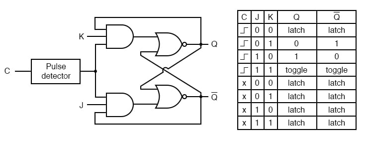
What used to be the S and R inputs are now called the J and K inputs, respectively. The old two-input AND gates have been replaced with 3-input AND gates, and the third input of each gate receives feedback from the Q and not-Q outputs.
What this does for us is permit the J input to have effect only when the circuit is reset, and permit the K input to have effect only when the circuit is set.
In other words, the two inputs are interlocked, to use a relay logic term, so that they cannot both be activated simultaneously.
If the circuit is “set,” the J input is inhibited by the 0 status of not-Q through the lower AND gate; if the circuit is “reset,” the K input is inhibited by the 0 status of Q through the upper AND gate.
When both J and K inputs are 1, however, something unique happens. Because of the selective inhibiting action of those 3-input AND gates, a “set” state inhibits input J so that the flip-flop acts as if J=0 while K=1 when in fact both are 1.
On the next clock pulse, the outputs will switch (“toggle”) from set (Q=1 and not-Q=0) to reset (Q=0 and not-Q=1). Conversely, a “reset” state inhibits input K so that the flip-flop acts as if J=1 and K=0 when in fact both are 1. The next clock pulse toggles the circuit again from reset to set.
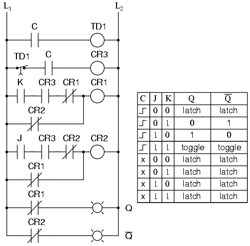
See if you can follow this logical sequence with the ladder logic equivalent of the J-K flip-flop:
The end result is that the S-R flip-flop’s “invalid” state is eliminated (along with the race condition it engendered) and we get a useful feature as a bonus: the ability to toggle between the two (bistable) output states with every transition of the clock input signal.
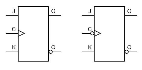
There is no such thing as a J-K latch, only J-K flip-flops. Without the edge-triggering of the clock input, the circuit would continuously toggle between its two output states when both J and K were held high (1), making it an astable device instead of a bistable device in that circumstance.
If we want to preserve bistable operation for all combinations of input states, we must use edge-triggering so that it toggles only when we tell it to, one step (clock pulse) at a time.
The block symbol for a J-K flip-flop is a whole lot less frightening than its internal circuitry, and just like the S-R and D flip-flops, J-K flip-flops come in two clock varieties (negative and positive edge-triggered):
REVIEW:
RELATED WORKSHEETS:

In Partnership with Future Electronics

by Jake Hertz

by Aaron Carman


