Flyback Switch Mode Regulator Calculator
A calculator for computing several parameters needed in the design of a flyback switch mode regulator
Outputs
Overview
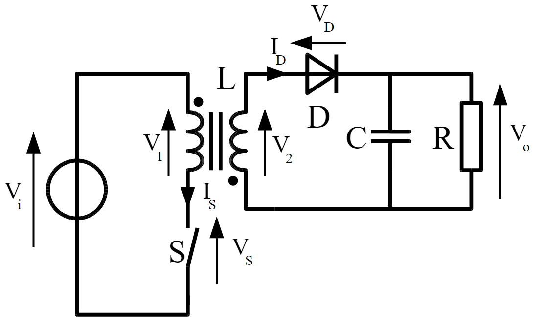
The flyback switch-mode regulator is one of the several switch-mode power supply topologies. This calculator is designed to compute for several parameters needed to design this type of regulator. Refer to the equations below to better understand which input parameter is needed to compute for a specific output parameter.
Equations
$$VT = I_{sat} L$$
$$DC = V_{out} V_{in} N$$
$$f_{min} = \frac{DC}{T_{ON_{max}}}$$
$$E_{cycle} = \frac{I_{sat}^{2} L}{2}$$
$$P_{max} = E_{cycle} f = \frac{I_{sat}^{2} L f}{2}$$
$$I_{out_{1}} = \frac{P_{max}}{V_{out_{1}}}$$
Where:
$$VT$$ = volt-time product
$$DC$$ = duty cycle
$$f_{min}$$ = minimum frequency
$$E_{cycle}$$ = energy per cycle
$$P_{max}$$ = maximum power
$$I_{out}$$ = output current
$$L$$ = transformer primary inductance
$$I_{sat}$$ = saturation current
$$T_{ON_{max}}$$ = wave high time
$$V_{out}$$ = output voltage
$$V_{in}$$ = input voltage
Applications
The flyback switch-mode converter is the most popular SMPS topology for designs that require no more than 150 watts of power. This topology offers a couple of advantages over other variations. First, the flyback switch-mode can operate over a wide input voltage range. Second, this topology can provide multiple isolated regulated voltages while only using one switching device. The disadvantage of the flyback switch-mode topology is the high voltage and current on the primary side switch and secondary diode.