
Comparator with Hysteresis (Schmitt Trigger) Calculator
This calculator will compute the required resistor ratio (R2/R1) and reference voltage (VREF) to create the desired high (VTH) and low (VTL) threshold voltages in a non-inverting comparator circuit with hysteresis (commonly called a Schmitt trigger).
Input
Calculate Vth and Vtl given R (=R2/R1) and Vref
Calculate R and Vref given Vth and Vtl
Overview
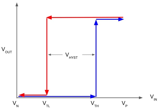
A comparator with hysteresis has a nonlinear response with different switching threshold voltages depending upon whether the input is transitioning from low to high, or high to low. The circuit employs positive feedback to generate the nonlinear response. The low-to-high transition input voltage is called the high threshold voltage (VTH). Similarly, the high-to-low transition input voltage is called the low threshold voltage (VTL). This calculator assumes that the output can swing from the positive supply rail (VP) to the negative supply rail (VN).
Circuit Design
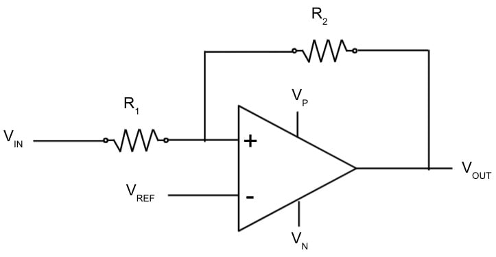
One common method for designing a comparator with hysteresis uses an operational amplifier and positive feedback from the output to the input as shown in the following figure. The hysteresis of this circuit is a function of the resistor ration (R2 / R1), the reference voltage (Vref), and the positive (Vp) and negative (Vn) supply voltages.
Equations
$$V_{TH} = (\frac{1 + R}{R})V_{REF} - (\frac{1}{R})V_{N}$$
$$V_{TL} = (\frac{1 + R}{R})V_{REF} - (\frac{1}{R})V_{P}$$
$$V_{REF} = V_N + (\frac{R}{1 + R})(V_{TH} - V_{N})$$
$$R = (\frac{(V_P - V_N)}{V_{TH} - V_{TL})}$$,
where:
VP = positive supply voltage
VN = negative supply voltage
VTH = high threshold voltage
VTL = low threshold voltage
VREF = reference voltage
R = resistance ratio (R2 / R1)
Applications
Hysteresis is often added to comparator circuits to minimize output noise or undersireable output transitions that occur with slowly varying or noisy input signals. For example, a traditional comparator circuit with a single switching point (i.e. no hysteresis) will "chatter" with extraneous output transitions when the input is near the switching point. A Schmitt triggers can eliminate this chatter. Schmitt triggers are also used in debouncing the outputs from mechanical switches and creating relaxation oscillators.


Some really nice and useful info on this website, also I conceive the design and style holds good features.
https://www.elpasotxautoglass.com/mobile-auto-glass-service-el-paso-texas-usa
In the calculator, the resistance ratios are stated incorrectly, it should read R2/R1. And not R1/R2.