
Op-Amp Voltage and Gain Calculator
A calculator for computing the gain and output voltage of an operational amplifier
Inverting Op Amp Gain
Non-Inverting Op Amp Gain
Overview
This calculator helps calculate the values of the output voltage and the inverting and non-inverting gains of an operational amplifier. Provide the values of the resistors, the input voltages, and the supply voltages and press the "calculate" button.
An operational amplifier (op-amp) is a voltage amplifier with a differential input and a single-ended output. The two most basic op-amp configurations are the inverting amplifier and the non-inverting amplifier. The terms "inverting" and "non-inverting" refer to the polarity of the output voltage with respect to that of the input voltage. An inverting amplifier provides an output voltage that has an opposite polarity to that of the input voltage. The non-inverting amplifier does not change the polarity of its input voltage.
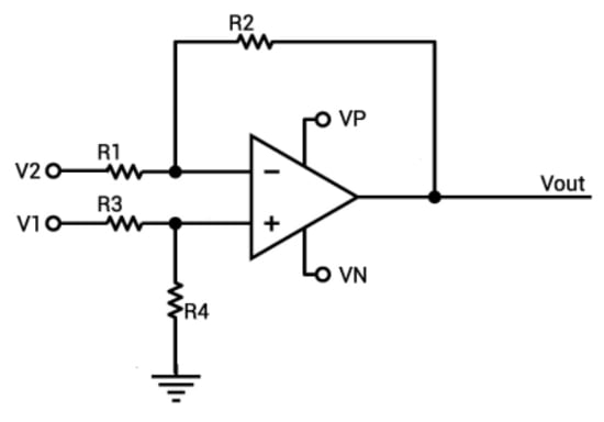
Note that this calculator can be used for either an inverting or a non-inverting op-amp configuration. For a non-inverting op-amp, set V2 to 0V and use V1 as the input. If an inverting op-amp is desired, set V1 to 0V and use V2 as the input. Use a very large value for R3 (e.g., 9999999999) if the op-amp's positive input terminal should be connected directly to ground.
Equations
$$V_{out}= A V_{input}$$
For inverting op-amp:
$$A = -\frac{R_{2}}{R_{1}}$$
For non-inverting op-amp:
$$A = 1 + \frac{R_{2}}{R_{1}}$$
Applications
An op-amp is a high-gain differential amplifier module that forms the central component in a variety of useful, straightforward amplifier circuits. Designing with op-amps is far simpler than creating customized amplifiers from discrete components, and the resulting circuits are easily fine-tuned according to the needs of the application. The fundamental technique in op-amp implementation is the use of negative feedback. In the typical inverting and non-inverting configurations, the feedback network takes the form of two resistors. The low-frequency gain of the finished circuit is almost entirely determined by the values of these two resistors.


I believe the above circuit has a mistake in that the inverting and non inverting inputs have been swapped probably by mistake but a non inverting amplifier would use v1 as input not v2 ! and the inverting (- input ) is often shown below rather than above, not that this matters but could have caused the mistake.