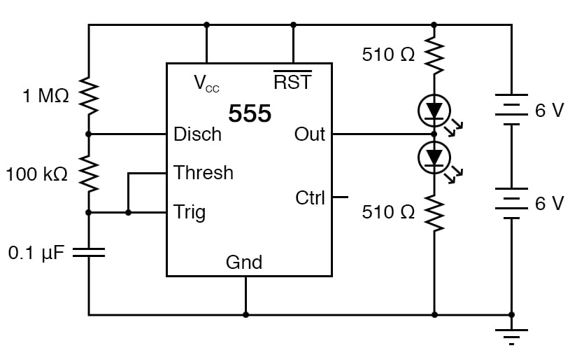
The 555 integrated circuit (IC) is a general-purpose timer useful for various functions. In this experiment, we explore its use as an astable multivibrator or oscillator. Connected to a capacitor and two resistors, as shown in Figure 1, it will oscillate freely, driving the light-emitting diodes (LEDs) on and off with a square-wave output voltage.
This circuit works on the principle of alternately charging and discharging a capacitor.
When the voltage detected at the threshold (THRESH) pin exceeds 2/3 of the power supply voltage (Vcc), the 555 begins to discharge the capacitor by grounding the discharge (DISCH) pin. It stops discharging the capacitor when the voltage detected by the trigger (TRIG) terminal falls below 1/3 of the power supply voltage. Thus, when both the THRESH and TRIGH terminals are connected to the capacitor’s positive terminal, the capacitor voltage will cycle between 1/3 and 2/3 power supply voltage in a sawtooth pattern.
During the charging cycle, the capacitor receives charging current through the series combination of the 1 MΩ and 100 kΩ resistors. As soon as the DISCH terminal on the 555 timer goes to ground potential (a transistor inside the 555 connected between that terminal and ground turns on), the capacitor’s discharging current only has to go through the 100 kΩ resistor. The result is an RC time constant that is much longer for charging than for discharging, resulting in a charging time greatly exceeding the discharging time.
The 555’s OUT terminal produces a square-wave voltage signal that is high (nearly Vcc) when the capacitor is charging and low (nearly 0 V) when the capacitor discharges. This alternating high/low voltage signal drives the two LEDs in opposite modes; when one is on, the other will be off.
Since the capacitor’s charging and discharging times are unequal, the high and low times of the output’s square-wave waveform will also be unequal. This can be seen in the relative brightness of the two LEDs; one will be much brighter than the other because it is on for a longer period of time during each cycle. The equality or inequality between the high and low times of a square wave is expressed as that wave’s duty cycle.
A square wave with a 50% duty cycle is perfectly symmetrical; its high time is precisely equal to its low time. A square wave that is high 10% of the time and low 90% of the time is said to have a 10% duty cycle.
An oscilloscope would be useful in analyzing the waveforms produced by this circuit, but it is not essential. An audio detector is a useful piece of test equipment for this experiment, especially if you don’t have an oscilloscope.
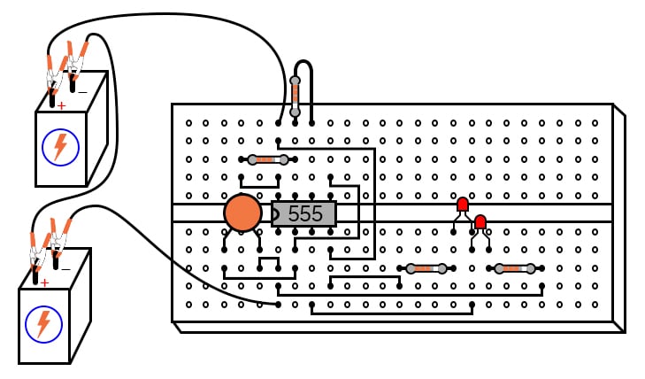
Step 1: Build the circuit illustrated in the schematic of Figure 1 and shown in the breadboard implementation of Figure 2.
Step 2: In this circuit, the output waveform has a high time exceeding the low time, resulting in a duty cycle greater than 50%. Therefore the lower LED should be brighter than the upper LED in the circuit. Is it?
Step 3: Use the audio detector (or an oscilloscope) to investigate the different voltage waveforms produced by this circuit.
Step 4: Try different resistor values and/or capacitor values to see what effects they have on output frequency or charge/discharge times.
Learn more about the fundamentals behind this project in the resources below.
Textbook:
Calculator:
Projects:
Worksheet:

In Partnership with Future Electronics

by Aaron Carman

by onsemi


by Advantech

