This project uses a 555 timer IC configured as an astable multivibrator, or oscillator, as illustrated in Figure 1.
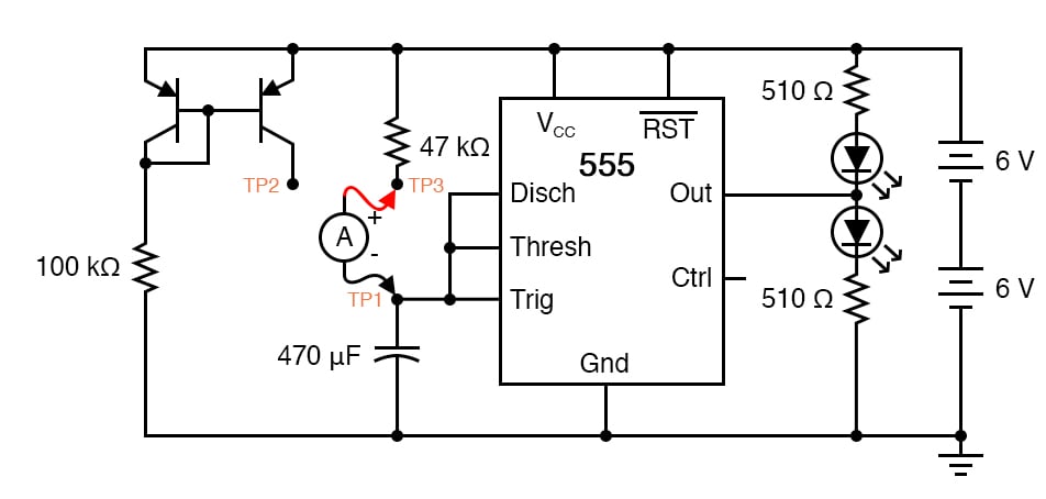
This time, however, we will compare its operation in two different capacitor-charging modes, traditional RC and constant-current.
In this circuit, the bottom light-emitting diode (LED) will be on when the output is high, and the top LED will be on when the output is low. If the 555 oscillation frequency is low, you may see this as the LEDs turning on and off. If the frequency is high, this can be seen in the relative brightness of the two LEDs; one will be much brighter than the other because it is on for a longer period of time during each cycle.
The voltage rating on the 470 µF capacitor is not critical so long as it generously exceeds the maximum power supply voltage. In this particular circuit, the maximum voltage is 12 V. Be sure you connect this capacitor in the circuit properly, respecting polarity.
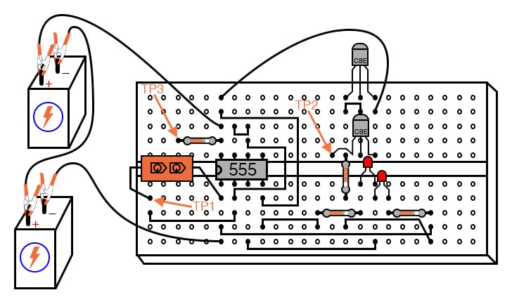
Step 1: Build the circuit illustrated in the schematic diagram of Figure 1 and shown implemented on a breadboard in Figure 2.
Step 2: Connect test point #1 (TP1) to test point #3 (TP3) using a jumper wire. This allows the capacitor to charge through a 47 kΩ resistor. When the capacitor has reached 2/3 supply voltage, the 555 timer switches to discharge mode and discharges the capacitor to a level of 1/3 supply voltage almost immediately. The charging cycle begins again at this point.
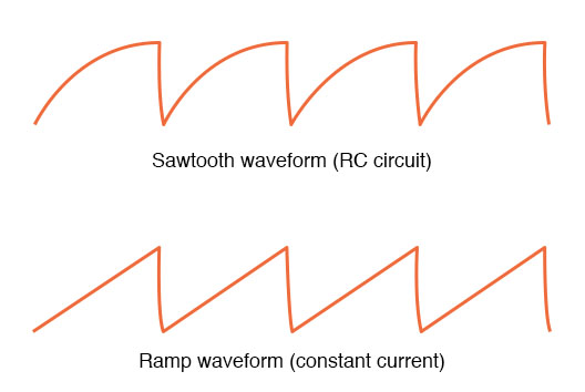
Step 3: Measure the voltage directly across the capacitor with a voltmeter (a digital voltmeter is preferred), and note the rate of capacitor charging over time. It should rise quickly at first, then taper off as it builds up to 2/3 supply voltage, just as you would expect from an RC charging circuit, as illustrated at the top of Figure 3.
Step 4: Remove the jumper wire from TP3, and re-connect it to TP2. This allows the capacitor to be charged through the controlled-current leg of a current mirror circuit formed by the two PNP transistors.
Step 5: Measure voltage directly across the capacitor again, noting the difference in charging rate over time as compared to the last circuit configuration. By connecting TP1 to TP2, the capacitor receives a nearly constant charging current. Constant capacitor charging current yields a voltage curve that is linear, as described by the equation: i = C(dV/dt).
If the capacitor current is constant, so will its rate-of-change of voltage over time. The result is a ramp waveform, as illustrated at the bottom of Figure 3.
Step 6: Measure the capacitor’s charging current directly by substituting an ammeter with the jumper wire. The ammeter will need to be set to measure a current in the range of hundreds of microamps (tenths of a milliamp). Connected between TP1 and TP3, you should see a current that starts at a relatively high value at the beginning of the charging cycle and tapers off toward the end. Connected between TP1 and TP2, however, the current will be much more stable.
Step 7: It is an interesting experiment at this point to change the temperature of either current mirror transistor by touching it with your finger. As the transistor warms, it will conduct more collector current for the same base-emitter voltage. If the controlling transistor (the one connected to the 100 kΩ resistor) is touched, the current decreases.If the controlled transistor is touched, the current increases. For the most stable current mirror operation, the two transistors should be cemented together so that their temperatures never differ substantially.
Step 8: This circuit works just as well at high frequencies as it does at low frequencies. Replace the 470 µF capacitor with a 0.1 µF capacitor, and use an audio detector or oscilloscope to sense the voltage waveform at the 555’s output terminal. The detector should produce an audio tone that is easy to hear.
Step 9: The capacitor’s voltage will now change much too fast to view with a voltmeter in the DC mode, but we can still measure capacitor current with an ammeter. With the ammeter connected between TP1 and TP3 (RC mode), measure both DC microamps and AC microamps. Record these current figures.
Step 10: Now, connect the ammeter between TP1 and TP2 (constant-current mode). Measure both DC microamps and AC microamps, noting any differences in current readings between this circuit configuration and the last one. Measuring AC current in addition to DC current is an easy way to determine which circuit configuration gives the most stable charging current.
If the current mirror circuit were perfect—the capacitor charging current absolutely constant—there would be zero AC current measured by the meter.
Learn more about the fundamentals behind this project in the resources below.
Textbook:
Capacitor Guide:
Projects:

In Partnership with Ymin

by Jake Hertz


by Avnet

