Series DC Circuits Practice Worksheet with Answers

Basic Electricity

PDF Version
  • Question 1

    In this circuit, three resistors receive the same amount of current (4 amps) from a single source. Calculate the amount of voltage “dropped” by each resistor, as well as the amount of power dissipated by each resistor:


    Reveal answer
  • Question 2

    The brightness of a light bulb - or the power dissipated by any electrical load, for that matter - may be varied by inserting a variable resistance in the circuit, like this:


    This method of electrical power control is not without its disadvantages, though. Consider an example where the circuit current is 5 amps, the variable resistance is 2 Ω, and the lamp drops 20 volts of voltage across its terminals. Calculate the power dissipated by the lamp, the power dissipated by the variable resistance, and the total power provided by the voltage source. Then, explain why this method of power control is not ideal.

    Reveal answer
  • Question 3

    A modern method of electrical power control involves inserting a fast-operating switch in-line with an electrical load, to switch power on and off to it very rapidly over time. Usually, a solid-state device such as a transistor is used:


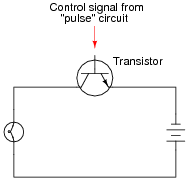
    This circuit has been greatly simplified from that of a real, pulse-control power circuit. Just the transistor is shown (and not the “pulse” circuit which is needed to command it to turn on and off) for simplicity. All you need to be aware of is the fact that the transistor operates like a simple, single-pole single-throw (SPST) switch, except that it is controlled by an electrical current rather than by a mechanical force, and that it is able to switch on and off millions of times per second without wear or fatigue.

    If the transistor is pulsed on and off fast enough, power to the light bulb may be varied as smoothly as if controlled by a variable resistor. However, there is very little energy wasted when using a fast-switching transistor to control electrical power, unlike when a variable resistance is used for the same task. This mode of electrical power control is commonly referred to as Pulse-Width Modulation, or PWM.

    Explain why PWM power control is much more efficient than controlling load power by using a series resistance.

    Reveal answer
  • Question 4

    Don’t just sit there! Build something!!


    Learning to mathematically analyze circuits requires much study and practice. Typically, students practice by working through lots of sample problems and checking their answers against those provided by the textbook or the instructor. While this is good, there is a much better way.

    You will learn much more by actually building and analyzing real circuits, letting your test equipment provide the “answers” instead of a book or another person. For successful circuit-building exercises, follow these steps:

    1. Carefully measure and record all component values prior to circuit construction.
    2. Draw the schematic diagram for the circuit to be analyzed.
    3. Carefully build this circuit on a breadboard or other convenient medium.
    4. Check the accuracy of the circuit’s construction, following each wire to each connection point, and verifying these elements one-by-one on the diagram.
    5. Mathematically analyze the circuit, solving for all values of voltage, current, etc.
    6. Carefully measure those quantities, to verify the accuracy of your analysis.
    7. If there are any substantial errors (greater than a few percent), carefully check your circuit’s construction against the diagram, then carefully re-calculate the values and re-measure.

    Avoid very high and very low resistor values, to avoid measurement errors caused by meter “loading”. I recommend resistors between 1 kΩ and 100 kΩ, unless, of course, the purpose of the circuit is to illustrate the effects of meter loading!

    One way you can save time and reduce the possibility of error is to begin with a very simple circuit and incrementally add components to increase its complexity after each analysis, rather than building a whole new circuit for each practice problem. Another time-saving technique is to re-use the same components in a variety of different circuit configurations. This way, you won’t have to measure any component’s value more than once.

    Reveal answer
  • Question 5

    The formula for calculating total resistance of three series-connected resistors is as follows:


    R = R1 + R2 + R3


    Algebraically manipulate this equation to solve for one of the series resistances (R1) in terms of the other two series resistances (R2 and R3) and the total resistance (R). In other words, write a formula that solves for R1 in terms of all the other variables.

    Reveal answer
  • Question 6

    Identify which of these circuits is a series circuit (there may be more than one shown!):


    Reveal answer
  • Question 7

    Most flashlights use multiple 1.5 volt batteries to power a light bulb with a voltage rating of several volts. Draw a schematic diagram of showing how multiple batteries may be connected to achieve a total voltage greater than any one of the batteries’ individual voltages.

    Reveal answer
  • Question 8

    A technician wants to energize a 24 volt motor, but lacks a 24 volt battery to do it with. Instead, she has access to several “power supply” units which convert 120 volt AC power from a power receptacle into low-voltage DC power that is adjustable over a range of 0 to 15 volts. Each of these power supplies is a box with a power cord, voltage adjustment knob, and two output terminals for connection with the DC voltage it produces:


    Draw a picture of how this technician might use power supplies to energize the 24 volt motor.

    Reveal answer
  • Question 9

    How much voltage does the light bulb receive in this circuit? Explain your answer.


    Also, identify the polarity of the voltage across the light bulb (mark with “ ” and “-” signs).

    Reveal answer
  • Question 10

    How much voltage does the light bulb receive in this circuit? Explain your answer.


    Also, identify the polarity of the voltage across the light bulb (mark with “ ” and “-” signs).

    Reveal answer
  • Question 11

    Re-draw this circuit in the form of a schematic diagram:


    Reveal answer
  • Question 12

    Suppose I connect two resistors in series with one another, like this:


    How much electrical resistance would you expect an ohmmeter to indicate if it were connected across the combination of these two series-connected resistors?


    Explain the reasoning behind your answer, and try to formulate a generalization for all combinations of series resistances.

    Reveal answer
  • Question 13

    What would happen if three 6-volt light bulbs were connected as shown to a 6-volt battery? How would their brightnesses compare to just having a single 6-volt light bulb connected to a 6-volt battery?


    Reveal answer
  • Question 14

    Qualitatively compare the voltage and current for each of the three light bulbs in this circuit (assume the three light bulbs are absolutely identical):


    Reveal answer
  • Question 15

    Explain, step by step, how to calculate the amount of current (I) that will go through each resistor in this series circuit, and also the voltage (V) dropped by each resistor:


    Reveal answer
  • Question 16

    Light-emitting diodes, or LEDs, are rugged and highly efficient sources of light. They are far more rugged and efficient than incandescent lamps, and they also have the ability to switch on and off much faster because there is no filament inside needing to heat or cool:


    LEDs are low voltage devices, typically rated in the range of 1.5 to 2 volts DC maximum. Single diodes generally draw low currents as well, about 20 milliamps each. The problem is, how do you operate an LED from a typical electronic power source, which may output 24 volts DC or more?


    The answer is to use a series dropping resistor:


    Calculate the necessary resistance value and minimum power rating of a series dropping resistor for an LED rated at 1.7 volts and 20 mA, and a power supply voltage of 24 volts.

    Reveal answer
  • Question 17

    Calculate the necessary series “dropping” resistor value to operate a 1.6 volt, 20 mA LED from a 15 volt DC power source. Also, calculate the power dissipated by the resistor while operating.

    R = PR =

    Reveal answer
  • Question 18

    Calculate the necessary series “dropping” resistor value to operate a 1.8 volt, 20 mA LED from a 34 volt DC power source. Also, calculate the power dissipated by the resistor while operating.

    R = PR =

    Reveal answer
  • Question 19

    Suppose that an electric heater, which is nothing more than a large resistor, dissipates 500 watts of power when directly connected to a 110 volt source:


    Now suppose that exact same heater is connected to one end of a long two-wire cable, which is then connected to the same 110 volt source. Assuming that each conductor within the cable has an end-to-end resistance of 3 ohms, how much power will the heater dissipate?


    Reveal answer
  • Question 20

    The circuit shown here is commonly referred to as a voltage divider. Calculate the voltage dropped across the following pairs of terminals, the current through each resistor, and the total amount of electrical resistance ßeen” by the 9-volt battery:


    • Voltage between terminals 2 and 3 =
    • Voltage between terminals 4 and 5 =
    • Voltage between terminals 6 and 7 =
    • Voltage between terminals 6 and 8 =
    • Voltage between terminals 4 and 8 =
    • Voltage between terminals 2 and 8 =
    • Current through each resistor =
    • Rtotal =

    Can you think of any practical applications for a circuit such as this?

    Reveal answer
  • Question 21

    What will happen in this circuit as the switches are sequentially turned on, starting with switch number 1 and ending with switch number 3?


    Describe how the successive closure of these three switches will impact:

    • The total amount of circuit resistance “seen” by the battery
    • The total amount of current drawn from the battery
    • The current through each resistor
    • The voltage drop across each resistor

    Also, provide a safety-related reason for the existence of the fourth resistor in this circuit, on the left-hand side of the circuit (not bypassed by any switch).

    Reveal answer
  • Question 22

    Complete the table of values for this circuit:


    Reveal answer
  • Question 23

    Complete the table of values for this circuit:


    Reveal answer
  • Question 24

    In a series circuit, certain general rules may be stated with regard to quantities of voltage, current, resistance, and power. Express these rules, using your own words:

    “In a series circuit, voltage . . .”

    “In a series circuit, current . . .”

    “In a series circuit, resistance . . .”

    “In a series circuit, power . . .”

    For each of these rules, explain why it is true.

    Reveal answer
  • Question 25

    Predict how all test point voltages (measured between each test point and ground) in this circuit will be affected as a result of the following faults. Consider each fault independently (i.e. one at a time, no multiple faults):


    • Resistor R1 fails open:
    • Resistor R2 fails open:
    • Resistor R3 fails open:
    • Solder bridge (short) past resistor R2:

    For each of these conditions, explain why the resulting effects will occur.

    Reveal answer
  • Question 26

    A student is troubleshooting a two-resistor voltage divider circuit, using a table to keep track of his test measurements and conclusions. The table lists all components and wires in the circuit so that the student may document their known status with each successive measurement:


    Measurement taken Battery Wire /1 R1 Wire 2/3 R2 Wire 4/-


    Prior to beginning troubleshooting, the student is told there is no voltage across R2. Thus, the very first entry into the table looks like this:


    Measurement taken Battery Wire /1 R1 Wire 2/3 R2 Wire 4/-

    VR2 = 0 V


    Based on this data, the student then determines possible faults which could cause this to happen, marking each possibility in the table using letters as symbols. The assumption here is that there is only one fault in the circuit, and that it is either a complete break (open) or a direct short:


    Measurement taken Battery Wire /1 R1 Wire 2/3 R2 Wire 4/-

    VR2 = 0 V O O O O S O


    “O” symbolizes a possible “open” fault, while “S” symbolizes a possible “shorted” fault.

    Next, the student measures between terminals 1 and 4, obtaining a full 6 volt reading. This is documented on the table as well, along with some updated conclusions regarding the status of all wires and components:


    Measurement taken Battery Wire /1 R1 Wire 2/3 R2 Wire 4/-

    VR2 = 0 V O O O O S O

    V1−4 = 6 V OK OK O O S OK


    After this, the student measures between terminals 1 and 2 (across resistor R1), and gets a reading of 0 volts. Complete the table based on this last piece of data:


    Measurement taken Battery Wire /1 R1 Wire 2/3 R2 Wire 4/-

    VR2 = 0 V O O O O S O

    V1−4 = 6 V OK OK O O S OK

    VR1 = 0 V


    Reveal answer
  • Question 27

    This voltage divider circuit has a problem: there is no voltage output between terminals 7 and 8.


    A technician has taken several measurements with a voltmeter, documenting them chronologically from top to bottom in the far-left column:


    Measurement Batt ( )/1 R1 2/3 R2 4/5 R3 6/7 R4 8/(-)

    V1−8 = 6 V

    V1−5 = 0 V

    V5−7 = 6 V


    Fill in all cells of this table with one of three different symbols, representing the status of each component or wire (numbers separated by a slash indicate the wire connecting those terminals):

    O for an “open” fault
    S for an “short” fault
    OK for no fault

    You are to assume that there is only one fault in this circuit, and that it is either a complete break (open) or a direct short (zero resistance). After completing the table, assess whether or not the exact fault may be known from the data recorded thus far. If not, suggest the next logical voltage measurement to take.

    Reveal answer
5 Comments
  • B
    beelzebob May 17, 2020

    llaboutcircuits.com/worksheets/series-dc-circuits/. In question 5, total series resistance is sum of each resistor, not product. Correct both question and answer

    Like. Reply
  • stefano.salari June 08, 2020

    Hello Everybody and thanks for your fantastic articles!

    I’m having troubles solving Excercise 19 of your Series circuits problems (https://www.allaboutcircuits.com/worksheets/series-dc-circuits/): For this excercise I’m getting a power dissipation for the heater of 403 W instead of 321.1 W.

    Since I’m learning electronics I’m surely doing something wrong… Here how I’m reasoning:

    1. With 110 V and a power dissipated of 500 W, I can calculate the current in the circuit, that should be I=P/V 500/110 = 4.545 A
    2. Knowing that the current in the circuit is 4.545 A I can use Ohm’s law to calculate the resistance of the heater: R=V/I 110/4.545 = 24 Ohm
    3. Now, longing the wires it’s the same as adding 6 Ohm of resistance, for a total resistance of 30 Ohm (24 + 6) so the current in the circuit will change accordingly. To find the new amount of current I use Ohm’s law once again: I=V/R 110/30 = 3.666 A
    4. Having a new current value of 3.666 A, I can now calculate power dissipation P=V*I 110*3.666 = 403 W

    Could you please help me understand where I’m wrong?

    Thank you so much!
    Stefano.

    Like. Reply
    • RK37 June 09, 2020
      The mistake is in step 4. When you multiply source voltage by current, you are calculating the power dissipation of the entire circuit. Instead, you need to calculate the power dissipation of only the heater, i.e., the 24.2 Ω resistor. You can use P = (I^2)R for this. You know the current through the heater, so square the current and multiply it by the heater resistance: I = 110 V/30.2 Ω = 3.642 A; P = (3.642 A)(3.642 A)(24.2 Ω) = 321 W.
      Like. Reply