Facebook
 Google
 GitHub
 Linkedin
Network Analysis Techniques
Component Modeling
5 questions By Tony R. Kuphaldt
-
Question 1 of 5
When plotted on a curve tracer, the characteristic curve for a normal PN junction rectifying diode looks something like this:
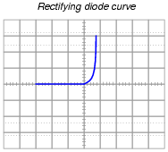
Label each axis (horizontal and vertical) of the curve tracer graph, then determine whether the diode behaves more like a voltage source or more like a current source (i.e. does it try to maintain constant voltage or does it try to maintain constant current?) when it is conducting current.
Models are very useful because they simplify circuit approximations. For example, we can analyze this diode circuit quite easily if we substitute an electrical source in place of the diode:
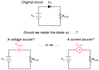
The only question here is, which substitution makes the most sense? Based on the diode’s characteristic curve behavior, should we substitute a voltage source or a current source in place of it? Assuming this is a 1N4001 rectifying diode, what is the value we should use for the substituting source?
Reveal answer
This behavior is similar to that of a voltage source once it is forward-biased and conducting current.
Follow-up question: quite obviously, diodes do not behave exactly as voltage sources. You cannot power anything off of a diode, for instance! Identify some of the limitations inherent to modeling diodes as voltage sources. Are there any instances you can think of where such a model could be misleading?
Notes:Modeling nonlinear semiconductor components in terms of linear, idealized passive components is a time-honored “trick” used to simplify circuit analysis. Like all “tricks” and analogies, this one has definite limitations. The follow-up question’s hint practically gives away examples of where such a model could be misleading!
-
Question 2 of 5
If we were to “model” a neon lamp with a standard passive component (resistor, voltage source, current source, capacitor, or inductor) for the sake of mathematically analyzing a circuit containing a neon lamp, what component would best represent the characteristics of the lamp within its “glow” region?

Reveal answerA neon lamp within its “glow” region would be best modeled by a voltage source.
Follow-up question: what component best models a neon lamp within the vertical (dashed-line) regions on the graph?
Notes:If your students are perplexed at the method of determining the answer, ask them this question: “For the neon lamp, what variable remains constant despite a wide variation in the other variable?”
-
Question 3 of 5
If we were to “model” a transistor with a standard passive component (resistor, voltage source, current source, capacitor, or inductor) for the sake of mathematically analyzing a circuit containing a transistor, what component would best represent the characteristics of the transistor within its “active” region?

Reveal answerA transistor within its “active” region would be best modeled by a current source.
Notes:If your students are perplexed at the method of determining the answer, ask them this question: “For the transistor, what variable remains constant despite a wide variation in the other variable?”