 Facebook
 Google
 GitHub
 Linkedin
Series R, L, and C
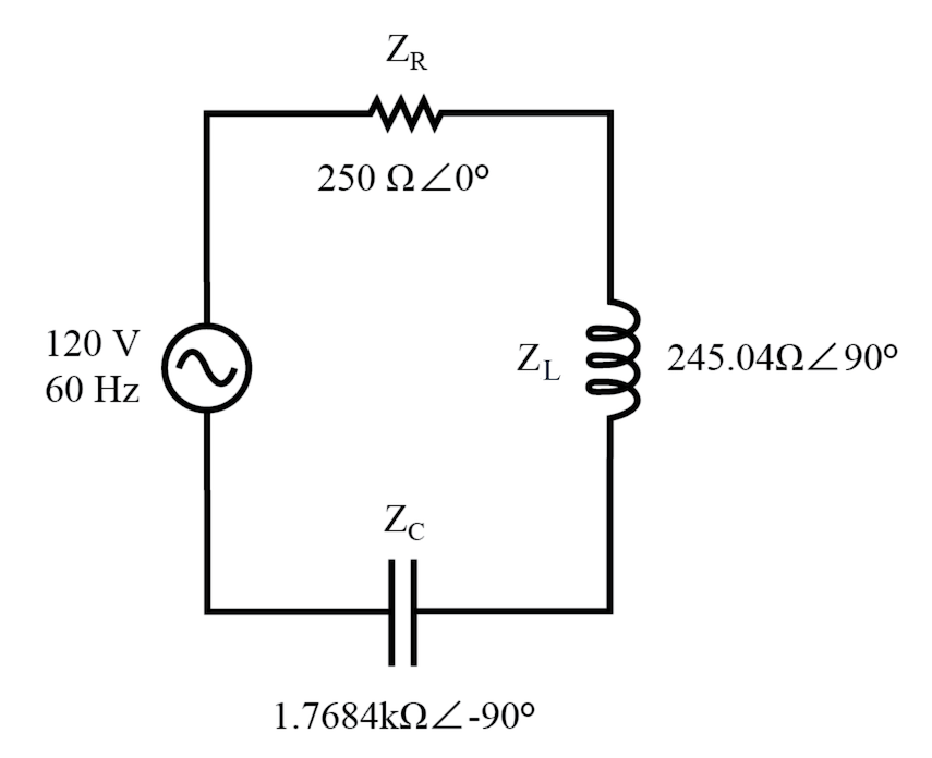
Let’s take the following example circuit and analyze it:

Example series R, L, and C circuit.
Solving for Reactance
The first step is to determine the reactance (in ohms) for the inductor and the capacitor.

The next step is to express all resistances and reactances in a mathematically common form: impedance. (Figure below)
Remember that an inductive reactance translates into a positive imaginary impedance (or an impedance at +90°), while a capacitive reactance translates into a negative imaginary impedance (impedance at -90°). Resistance, of course, is still regarded as a purely “real” impedance (polar angle of 0°):

Example series R, L, and C circuit with component values replaced by impedances.
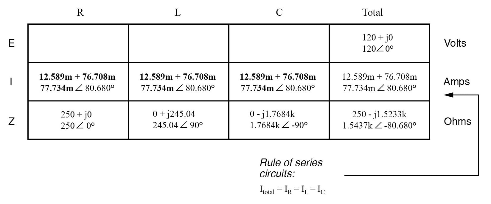
Tabulate Results:
Now, with all quantities of opposition to electric current expressed in a common, complex number format (as impedances, and not as resistances or reactances), they can be handled in the same way as plain resistances in a DC circuit.
This is an ideal time to draw up an analysis table for this circuit and insert all the “given” figures (total voltage, and the impedance of the resistor, inductor, and capacitor).

Unless otherwise specified, the source voltage will be our reference for phase shift, and so will be written at an angle of 0°. Remember that there is no such thing as an “absolute” angle of phase shift for a voltage or current, since its always a quantity relative to another waveform.
Phase angles for impedance, however (like those of the resistor, inductor, and capacitor), are known absolutely, because the phase relationships between voltage and current at each component are absolutely defined.
Notice that I’m assuming a perfectly reactive inductor and capacitor, with impedance phase angles of exactly +90 and -90°, respectively.
Although real components won’t be perfect in this regard, they should be fairly close. For simplicity, I’ll assume perfectly reactive inductors and capacitors from now on in my example calculations except where noted otherwise.
Since the above example circuit is a series circuit, we know that the total circuit impedance is equal to the sum of the individuals, so:

Inserting this figure for total impedance into our table:

We can now apply Ohm’s Law (I=E/R) vertically in the “Total” column to find total current for this series circuit:

Being a series circuit, the current must be equal through all components. Thus, we can take the figure obtained for total current and distribute it to each of the other columns:
Now we’re prepared to apply Ohm’s Law (E=IZ) to each of the individual component columns in the table, to determine voltage drops:

Notice something strange here: although our supply voltage is only 120 volts, the voltage across the capacitor is 137.46 volts! How can this be? The answer lies in the interaction between the inductive and capacitive reactances.
Expressed as impedances, we can see that the inductor opposes current in a manner precisely opposite that of the capacitor. Expressed in rectangular form, the inductor’s impedance has a positive imaginary term and the capacitor has a negative imaginary term.
When these two contrary impedances are added (in series), they tend to cancel each other out! Although they’re still added together to produce a sum, that sum is actually less than either of the individual (capacitive or inductive) impedances alone.
It is analogous to adding together a positive and a negative (scalar) number: the sum is a quantity less than either one’s individual absolute value.
If the total impedance in a series circuit with both inductive and capacitive elements is less than the impedance of either element separately, then the total current in that circuit must be greater than what it would be with only the inductive or only the capacitive elements there.
With this abnormally high current through each of the components, voltages greater than the source voltage may be obtained across some of the individual components! Further consequences of inductors’ and capacitors’ opposite reactances in the same circuit will be explored in the next chapter.
Once you’ve mastered the technique of reducing all component values to impedances (Z), analyzing any AC circuit is only about as difficult as analyzing any DC circuit, except that the quantities dealt with are vector instead of a scalar.
With the exception of equations dealing with power (P), equations in AC circuits are the same as those in DC circuits, using impedances (Z) instead of resistances (R). Ohm’s Law (E=IZ) still holds true, and so do Kirchhoff’s Voltage and Current Laws.
To demonstrate Kirchhoff’s Voltage Law in an AC circuit, we can look at the answers we derived for component voltage drops in the last circuit. KVL tells us that the algebraic sum of the voltage drops across the resistor, inductor, and capacitor should equal the applied voltage from the source.
Even though this may not look like it is true at first sight, a bit of complex number addition proves otherwise:

Aside from a bit of rounding error, the sum of these voltage drops does equal 120 volts. Performed on a calculator (preserving all digits), the answer you will receive should be exactly 120 + j0 volts.
We can also use SPICE to verify our figures for this circuit:

Example series R, L, and C SPICE circuit.
r1 1 2 250
 l1 2 3 650m
 c1 3 0 1.5u
 .ac lin 1 60 60
 .print ac v(1,2) v(2,3) v(3,0) i(v1)
 .print ac vp(1,2) vp(2,3) vp(3,0) ip(v1)
 .end
 freq            v(1,2)          v(2,3)          v(3)            i(v1)
 6.000E+01       1.943E+01       1.905E+01       1.375E+02       7.773E-02

 freq            vp(1,2)         vp(2,3)         vp(3)           ip(v1)
 6.000E+01       8.068E+01       1.707E+02       -9.320E+00       -9.932E+01

The SPICE simulation shows our hand-calculated results to be accurate.
As you can see, there is little difference between AC circuit analysis and DC circuit analysis, except that all quantities of voltage, current, and resistance (actually, impedance) must be handled in complex rather than scalar form so as to account for phase angle.
This is good since it means all you’ve learned about DC electric circuits applies to what you’re learning here. The only exception to this consistency is the calculation of power, which is so unique that it deserves a chapter devoted to that subject alone.
REVIEW:
- Impedances of any kind add in series: ZTotal = Z1 + Z2 + . . . Zn
- Although impedances add in series, the total impedance for a circuit containing both inductance and capacitance may be less than one or more of the individual impedances, because series inductive and capacitive impedances tend to cancel each other out. This may lead to voltage drops across components exceeding the supply voltage!
- All rules and laws of DC circuits apply to AC circuits, so long as values are expressed in complex form rather than a scalar. The only exception to this principle is the calculation of power, which is very different for AC.
RELATED WORKSHEET:


Correction: Rule of series circuit: Itotal = IR = IL = IC
how did it became 1.5437 kohms?