Facebook
 Google
 GitHub
 Linkedin
AC Electric Circuits
Series-Parallel Combination AC Circuits
26 questions By Tony R. Kuphaldt
-
Question 1 of 26
Don’t just sit there! Build something!! Learning to mathematically analyze circuits requires much study and practice. Typically, students practice by working through lots of sample problems and checking their answers against those provided by the textbook or the instructor. While this is good, there is a much better way.
You will learn much more by actually building and analyzing real circuits, letting your test equipment provide the “answers” instead of a book or another person. For successful circuit-building exercises, follow these steps:
- Carefully measure and record all component values prior to circuit construction.
- Draw the schematic diagram for the circuit to be analyzed.
- Carefully build this circuit on a breadboard or other convenient medium.
- Check the accuracy of the circuit’s construction, following each wire to each connection point, and verifying these elements one-by-one on the diagram.
- Mathematically analyze the circuit, solving for all voltage and current values.
- Carefully measure all voltages and currents, to verify the accuracy of your analysis.
- If there are any substantial errors (greater than a few percent), carefully check your circuit’s construction against the diagram, then carefully re-calculate the values and re-measure.
For AC circuits where inductive and capacitive reactances (impedances) are a significant element in the calculations, I recommend high quality (high-Q) inductors and capacitors, and powering your circuit with low frequency voltage (power-line frequency works well) to minimize parasitic effects. If you are on a restricted budget, I have found that inexpensive electronic musical keyboards serve well as “function generators” for producing a wide range of audio-frequency AC signals. Be sure to choose a keyboard “voice” that closely mimics a sine wave (the “panflute” voice is typically good), if sinusoidal waveforms are an important assumption in your calculations.
As usual, avoid very high and very low resistor values, to avoid measurement errors caused by meter “loading”. I recommend resistor values between 1 kΩ and 100 kΩ.
One way you can save time and reduce the possibility of error is to begin with a very simple circuit and incrementally add components to increase its complexity after each analysis, rather than building a whole new circuit for each practice problem. Another time-saving technique is to re-use the same components in a variety of different circuit configurations. This way, you won’t have to measure any component’s value more than once.
Reveal answerLet the electrons themselves give you the answers to your own “practice problems”!
Notes:It has been my experience that students require much practice with circuit analysis to become proficient. To this end, instructors usually provide their students with lots of practice problems to work through and provide answers for students to check their work against. While this approach makes students proficient in circuit theory, it fails to fully educate them.
Students don’t just need mathematical practice. They also need real, hands-on practice building circuits and using test equipment. So, I suggest the following alternative approach: students should build their own “practice problems” with real components, and try to mathematically predict the various voltage and current values. This way, the mathematical theory “comes alive,” and students gain practical proficiency they wouldn’t gain merely by solving equations.
Another reason for following this method of practice is to teach students scientific method: the process of testing a hypothesis (in this case, mathematical predictions) by performing a real experiment. Students will also develop real troubleshooting skills as they occasionally make circuit construction errors.
Spend a few moments of time with your class to review some of the “rules” for building circuits before they begin. Discuss these issues with your students in the same Socratic manner you would normally discuss the worksheet questions, rather than simply telling them what they should and should not do. I never cease to be amazed at how poorly students grasp instructions when presented in a typical lecture (instructor monolog) format!
An excellent way to introduce students to the mathematical analysis of real circuits is to have them first determine component values (L and C) from measurements of AC voltage and current. The simplest circuit, of course, is a single component connected to a power source! Not only will this teach students how to set up AC circuits properly and safely, but it will also teach them how to measure capacitance and inductance without specialized test equipment.
A note on reactive components: use high-quality capacitors and inductors, and try to use low frequencies for the power supply. Small step-down power transformers work well for inductors (at least two inductors in one package!), so long as the voltage applied to any transformer winding is less than that transformer’s rated voltage for that winding (in order to avoid saturation of the core).
A note to those instructors who may complain about the “wasted” time required to have students build real circuits instead of just mathematically analyzing theoretical circuits:
What is the purpose of students taking your course?
If your students will be working with real circuits, then they should learn on real circuits whenever possible. If your goal is to educate theoretical physicists, then stick with abstract analysis, by all means! But most of us plan for our students to do something in the real world with the education we give them. The “wasted” time spent building real circuits will pay huge dividends when it comes time for them to apply their knowledge to practical problems.
Furthermore, having students build their own practice problems teaches them how to perform primary research, thus empowering them to continue their electrical/electronics education autonomously.
In most sciences, realistic experiments are much more difficult and expensive to set up than electrical circuits. Nuclear physics, biology, geology, and chemistry professors would just love to be able to have their students apply advanced mathematics to real experiments posing no safety hazard and costing less than a textbook. They can’t, but you can. Exploit the convenience inherent to your science, and get those students of yours practicing their math on lots of real circuits!
-
Question 2 of 26
Calculate the line current and power factor in this AC power system:

Now, calculate the line current and power factor for the same circuit after the addition of a capacitor in parallel with the load:
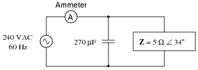
Reveal answer- Without capacitor
- Iline = 48 A
- P.F. = 0.829
- With capacitor
- Iline = 39.87 A
- P.F. = 0.998
Follow-up question: does the addition of the capacitor affect the amount of current through the 5 Ω load? Why or why not?
Notes:The answers to this question may seem really strange to students accustomed to DC circuit calculations, where parallel branch currents always add up to a greater total. With complex numbers, however, the sum is not necessarily greater than the individual values!
-
Question 3 of 26
It is often useful in AC circuit analysis to be able to convert a series combination of resistance and reactance into an equivalent parallel combination of conductance and susceptance, or visa-versa:

We know that resistance (R), reactance (X), and impedance (Z), as scalar quantities, relate to one another trigonometrically in a series circuit. We also know that conductance (G), susceptance (B), and admittance (Y), as scalar quantities, relate to one another trigonometrically in a parallel circuit:

If these two circuits are truly equivalent to one another, having the same total impedance, then their representative triangles should be geometrically similar (identical angles, same proportions of side lengths). With equal proportions, R/Z in the series circuit triangle should be the same ratio as G/Y in the parallel circuit triangle, that is R/Z = G/Y.
Building on this proportionality, prove the following equation to be true:
Rseries Rparallel = Ztotal2 After this, derive a similar equation relating the series and parallel reactances (Xseries and Xparallel) with total impedance (Ztotal).
Reveal answerI’ll let you figure out how to turn R/Z = G/Y into Rseries Rparallel = Ztotal2 on your own!
As for the reactance relation equation, here it is:
Xseries Xparallel = Ztotal2 Notes:Being able to convert between series and parallel AC networks is a valuable skill for analyzing complex series-parallel combination circuits, because it means any series-parallel combination circuit may then be converted into an equivalent simple-series or simple-parallel, which is mush easier to analyze.
Some students might ask why the conductance/susceptance triangle is “upside-down” compared to the resistance/reactance triangle. The reason has to do with the sign reversal of imaginary quantities when inverted: 1/j = −j. The phase angle of a pure inductance’s impedance is 90 degrees, while the phase angle of the same (pure) inductance’s admittance is -90 degrees, due to reciprocation. Thus, while the X leg of the resistance/reactance triangle points up, the B leg of the conductance/susceptance triangle must point down.


Related Tools:
- Algebraic Substitution for Electric Circuits
- Performance-Based Assessments for Basic Electricity Competencies