Facebook
 Google
 GitHub
 Linkedin
Contactors
All About Contactors
When a relay is used to switch a large amount of electrical power through its contacts, it is designated by a special name: contactor. Contactors typically have multiple contacts, and those contacts are usually (but not always) normally-open, so that power to the load is shut off when the coil is de-energized.
Perhaps the most common industrial use for contactors is the control of electric motors.

The top three contacts switch the respective phases of the incoming 3-phase AC power, typically at least 480 Volts for motors 1 horsepower or greater. The lowest contact is an “auxiliary” contact which has a current rating much lower than that of the large motor power contacts, but is actuated by the same armature as the power contacts.
The auxiliary contact is often used in a relay logic circuit, or for some other part of the motor control scheme, typically switching 120 Volt AC power instead of the motor voltage. One contactor may have several auxiliary contacts, either normally-open or normally-closed if required.
Overload Heaters
The three “opposed-question-mark” shaped devices in series with each phase going to the motor are called overload heaters. Each “heater” element is a low-resistance strip of metal intended to heat up as the motor draws current.
If the temperature of any of these heater elements reaches a critical point (equivalent to a moderate overloading of the motor), a normally-closed switch contact (not shown in the diagram) will spring open. This normally-closed contact is usually connected in series with the relay coil, so that when it opens the relay will automatically de-energize, thereby shutting off power to the motor.
We will see more of this overload protection wiring in the next chapter.
Overload heaters are intended to provide overcurrent protection for large electric motors, unlike circuit breakers and fuses which serve the primary purpose of providing overcurrent protection for power conductors.
Functions of Overload Heaters
Overload heater function is often misunderstood. They are not fuses; that is, it is not their function to burn open and directly break the circuit as a fuse is designed to do. Rather, overload heaters are designed to thermally mimic the heating characteristic of the particular electric motor to be protected.
All motors have thermal characteristics, including the amount of heat energy generated by resistive dissipation (I2R), the thermal transfer characteristics of heat “conducted” to the cooling medium through the metal frame of the motor, the physical mass and specific heat of the materials constituting the motor, etc.
These characteristics are mimicked by the overload heater on a miniature scale: when the motor heats up toward its critical temperature, so will the heater toward its critical temperature, ideally at the same rate and approach curve.
Thus, the overload contact, in sensing heater temperature with a thermomechanical mechanism, will sense an analog of the real motor. If the overload contact trips due to excessive heater temperature, it will be an indication that the real motor has reached its critical temperature (or, would have done so in a short while).
After tripping, the heaters are supposed to cool down at the same rate and approach curve as the real motor, so that they indicate an accurate proportion of the motor’s thermal condition, and will not allow power to be re-applied until the motor is truly ready for start-up again.
Three-Phase Electric Motor Contactor
Shown here is a contactor for a three-phase electric motor, installed on a panel as part of an electrical control system at a municipal water treatment plant:

Sample Contactors
Three-phase, 480 volt AC power comes into the three normally-open contacts at the top of the contactor via screw terminals labeled “L1,” “L2,” and “L3” (The “L2” terminal is hidden behind a square-shaped “snubber” circuit connected across the contactor’s coil terminals). Power to the motor exits the overload heater assembly at the bottom of this device via screw terminals labeled “T1,” “T2,” and “T3.”
The overload heater units themselves are black, square-shaped blocks with the label “W34,” indicating a particular thermal response for a certain horsepower and temperature rating of the electric motor.
If an electric motor of differing power and/or temperature ratings were to be substituted for the one presently in service, the overload heater units would have to be replaced with units having a thermal response suitable for the new motor. The motor manufacturer can provide information on the appropriate heater units to use.
A white push button located between the “T1” and “T2” line heaters serves as a way to manually reset the normally-closed switch contact back to its normal state after having been tripped by excessive heater temperature.
Wire connections to the “overload” switch contact may be seen at the lower-right of the photograph, near a label reading “NC” (normally-closed). On this particular overload unit, a small “window” with the label “Tripped” indicates a tripped condition by means of a colored flag. In this photograph, there is no “tripped” condition, and the indicator appears clear.
Heater Elements as a Crude Current Shunt Resistor
As a footnote, heater elements may be used as a crude current shunt resistor for determining whether or not a motor is drawing current when the contactor is closed. There may be times when you’re working on a motor control circuit, where the contactor is located far away from the motor itself.
How do you know if the motor is consuming power when the contactor coil is energized and the armature has been pulled in? If the motor’s windings are burnt open, you could be sending voltage to the motor through the contactor contacts, but still, have zero current, and thus no motion from the motor shaft.
If a clamp-on ammeter isn’t available to measure line current, you can take your multimeter and measure millivoltage across each heater element: if the current is zero, the voltage across the heater will be zero (unless the heater element itself is open, in which case the voltage across it will be large); if there is current going to the motor through that phase of the contactor, you will read a definite millivoltage across that heater:
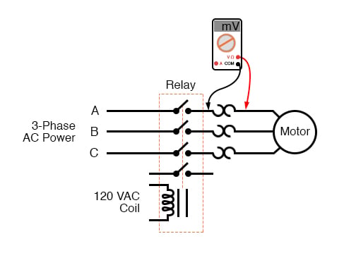
This is an especially useful trick to use for troubleshooting 3-phase AC motors, to see if one phase winding is burnt open or disconnected, which will result in a rapidly destructive condition known as “single-phasing.”
If one of the lines carrying power to the motor is open, it will not have any current through it (as indicated by a 0.00 mV reading across its heater), although the other two lines will (as indicated by small amounts of voltage dropped across the respective heaters).
REVIEW:
- A contactor is a large relay, usually used to switch current to an electric motor or another high-power load.
- Large electric motors can be protected from overcurrent damage through the use of overload heaters and overload contacts. If the series-connected heaters get too hot from excessive current, the normally-closed overload contact will open, de-energizing the contactor sending power to the motor.
RELATED WORKSHEETS: