 Facebook
 Google
 GitHub
 Linkedin
AC Electric Circuits
AC Motor Control Circuits
23 questions By Tony R. Kuphaldt
-
Question 1 of 23
Perhaps the most challenging aspect of interpreting ladder diagrams, for people more familiar with electronic schematic diagrams, is how electromechanical relays are represented. Compare these two equivalent diagrams:
First, the ladder diagram:

Next, the schematic diagram:

Based on your observations of these two diagrams, explain how electromechanical relays are represented differently between ladder and schematic diagrams.
Reveal answerOne of the most significant differences is that in ladder diagrams, relay coils and relay contacts (the normally-open contact in this diagram shown as a capacitor-like symbol) need not be drawn near each other.
Follow-up question: what do the two labels “L1” and “L2” represent?
Notes:Discuss these diagrams with your students, noting any significant advantages and disadvantages of each convention.
In reference to the challenge question, the symbols “L1” and “L2” are very common designations for AC power conductors. Be sure your students have researched this and know what these labels mean!
-
Question 2 of 23
Interpret this AC motor control circuit diagram, explaining the meaning of each symbol:
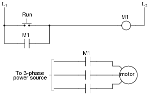
Also, explain the operation of this motor control circuit. What happens when someone actuates the “Run” switch? What happens when they let go of the “Run” switch?
Reveal answerIn this circuit, the motor will start once the “Run” switch is actuated. When the “Run” switch is released, the motor continues to run.
Follow-up question: this circuit has no “stop” switch! What would have to be modified in the ladder logic circuit to provide “stop” control?
Notes:This circuit is known as a latching circuit, because it “latches” in the “on” state after a momentary action. The contact in parallel with the “Run” switch is often referred to as a seal-in contact, because it “seals” the momentary condition of the Run switch closure after that switch is de-actuated.
The follow-up question of how we may make the motor stop running is a very important one. Spend time with your students discussing this practical design problem, and implement a solution.
-
Question 3 of 23
Draw the necessary wire connections to build the circuit shown in this ladder diagram:
Ladder diagram:

Illustration showing components:

Reveal answer
Notes:This question helps students build their spatial-relations skills, as they relate a neat, clean diagram to a relatively “messy” real-world circuit. As usual, the circuit shown here is not the only way it could have been built, but it is one solution.


Hello, sir.
Please share the name of the Source material/ Text book used in this Article. I will be very thankful to you.
Thanks for doing such a great job.
Good day.
Please I’m Benjamin Akrofi and I need answers to question 8
The name of the site I saw the question is ALL ABOUT CIRCUITS