 Facebook
 Google
 GitHub
 Linkedin
DC Electric Circuits
Series-Parallel DC Circuits
41 questions By Tony R. Kuphaldt
-
Question 1 of 41
Don’t just sit there! Build something!! Learning to mathematically analyze circuits requires much study and practice. Typically, students practice by working through lots of sample problems and checking their answers against those provided by the textbook or the instructor. While this is good, there is a much better way.
You will learn much more by actually building and analyzing real circuits, letting your test equipment provide the “answers” instead of a book or another person. For successful circuit-building exercises, follow these steps:
- Carefully measure and record all component values prior to circuit construction.
- Draw the schematic diagram for the circuit to be analyzed.
- Carefully build this circuit on a breadboard or other convenient medium.
- Check the accuracy of the circuit’s construction, following each wire to each connection point, and verifying these elements one-by-one on the diagram.
- Mathematically analyze the circuit, solving for all values of voltage, current, etc.
- Carefully measure those quantities, to verify the accuracy of your analysis.
- If there are any substantial errors (greater than a few percent), carefully check your circuit’s construction against the diagram, then carefully re-calculate the values and re-measure.
Avoid very high and very low resistor values, to avoid measurement errors caused by meter “loading”. I recommend resistors between 1 kΩ and 100 kΩ, unless, of course, the purpose of the circuit is to illustrate the effects of meter loading!
One way you can save time and reduce the possibility of error is to begin with a very simple circuit and incrementally add components to increase its complexity after each analysis, rather than building a whole new circuit for each practice problem. Another time-saving technique is to re-use the same components in a variety of different circuit configurations. This way, you won’t have to measure any component’s value more than once.
Reveal answerLet the electrons themselves give you the answers to your own “practice problems”!
Notes:It has been my experience that students require much practice with circuit analysis to become proficient. To this end, instructors usually provide their students with lots of practice problems to work through, and provide answers for students to check their work against. While this approach makes students proficient in circuit theory, it fails to fully educate them.
Students don’t just need mathematical practice. They also need real, hands-on practice building circuits and using test equipment. So, I suggest the following alternative approach: students should build their own “practice problems” with real components, and try to mathematically predict the various voltage and current values. This way, the mathematical theory “comes alive,” and students gain practical proficiency they wouldn’t gain merely by solving equations.
Another reason for following this method of practice is to teach students scientific method: the process of testing a hypothesis (in this case, mathematical predictions) by performing a real experiment. Students will also develop real troubleshooting skills as they occasionally make circuit construction errors.
Spend a few moments of time with your class to review some of the “rules” for building circuits before they begin. Discuss these issues with your students in the same Socratic manner you would normally discuss the worksheet questions, rather than simply telling them what they should and should not do. I never cease to be amazed at how poorly students grasp instructions when presented in a typical lecture (instructor monologue) format!
A note to those instructors who may complain about the “wasted” time required to have students build real circuits instead of just mathematically analyzing theoretical circuits:
What is the purpose of students taking your course?
If your students will be working with real circuits, then they should learn on real circuits whenever possible. If your goal is to educate theoretical physicists, then stick with abstract analysis, by all means! But most of us plan for our students to do something in the real world with the education we give them. The “wasted” time spent building real circuits will pay huge dividends when it comes time for them to apply their knowledge to practical problems.
Furthermore, having students build their own practice problems teaches them how to perform primary research, thus empowering them to continue their electrical/electronics education autonomously.
In most sciences, realistic experiments are much more difficult and expensive to set up than electrical circuits. Nuclear physics, biology, geology, and chemistry professors would just love to be able to have their students apply advanced mathematics to real experiments posing no safety hazard and costing less than a textbook. They can’t, but you can. Exploit the convenience inherent to your science, and get those students of yours practicing their math on lots of real circuits!
-
Question 2 of 41
In a series circuit, certain general rules may be stated with regard to quantities of voltage, current, resistance, and power. Express these rules, using your own words:
“In a series circuit, voltage . . .”
“In a series circuit, current . . .”
“In a series circuit, resistance . . .”
“In a series circuit, power . . .”
For each of these rules, explain why it is true.
Reveal answer“In a series circuit, voltage drops add to equal the total.”
“In a series circuit, current is equal through all components.”
“In a series circuit, resistances add to equal the total.”
“In a series circuit, power dissipations add to equal the total.”
Notes:Rules of series and parallel circuits are very important for students to comprehend. However, a trend I have noticed in many students is the habit of memorizing rather than understanding these rules. Students will work hard to memorize the rules without really comprehending why the rules are true, and therefore often fail to recall or apply the rules properly.
An illustrative technique I have found very useful is to have students create their own example circuits in which to test these rules. Simple series and parallel circuits pose little challenge to construct, and therefore serve as excellent learning tools. What could be better, or more authoritative, than learning principles of circuits from real experiments? This is known as primary research, and it constitutes the foundation of scientific inquiry. The greatest problem you will have as an instructor is encouraging your students to take the initiative to build these demonstration circuits on their own, because they are so used to having teachers simply tell them how things work. This is a shame, and it reflects poorly on the state of modern education.
-
Question 3 of 41
From observation of this circuit (with components attached to a “terminal strip”), draw an appropriate schematic diagram:
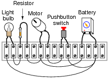
Reveal answer
Notes:This type of question is one that lends itself well to students drawing their answers on the board in front of class. The skill of transferring a real circuit into a cleanly-drawn schematic is one that some students struggle mightily with, but it is important. Those students will want to know what technique(s) may be used to make the transfer. Students who are more spatially adept will probably have a couple of different ways to approach a problem such as this. Allow them to explain to the rest of the class their technique(s) for tracing the real circuit’s wiring into a schematic diagram.
Giving students the opportunity to teach their peers is a powerful instructional method, and should be encouraged at all times!


How did you guys find the answer for Q5, figure 6