 Facebook
 Google
 GitHub
 Linkedin
What is the Difference Between Series and Parallel Circuits?
What are Series and Parallel Circuits?
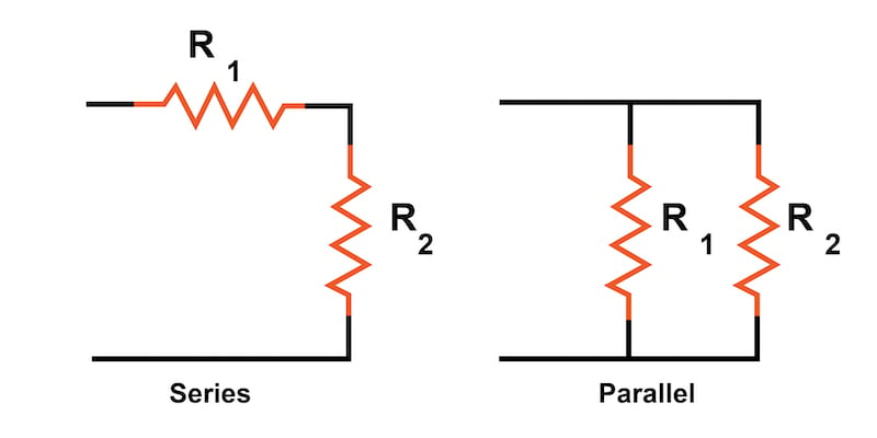
In a series circuit, all components are connected end-to-end to form a single path for current flow. In a parallel circuit, all components are connected across each other with exactly two electrically common nodes with the same voltage across each component.
Circuits consisting of just one battery and one load resistance are very simple to analyze, but they are not often found in practical applications. Usually, we find circuits where more than two components are connected together.
There are two fundamental ways in which to connect more than two circuit components: series and parallel. These two basic connection methods can be combined to create more complex series-parallel circuits.
What is a Series Connection?
The definition of a series circuit is a circuit where the components are connected end-to-end in a line as illustrated in Figure 1.
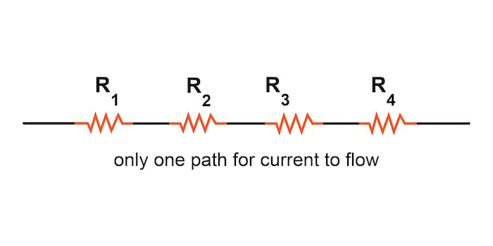
Figure 1. Series connection of resistors
These series resistors form a single path through which current can flow.
Introduction to Series Circuits—A Series Circuit Example
Now, let’s examine an example of a series circuit as shown in Figure 2:
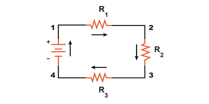
Figure 2. An example of a series circuit.
Here, we have three resistors (labeled R1, R2, and R3) connected in a long chain from one battery terminal to the other. Each resistor in a series circuit shares one electrical node with its nearest neighbor.
Note: The subscript labels—those little numbers to the lower-right of the letter “R”—are unrelated to the resistor values in ohms. They serve only to identify one resistor from another.
A series circuit’s defining characteristic is that all components in a series circuit have the same current flowing through them. There is only one path for the current to flow. In the circuit from Figure 2, the current (I) flows clockwise to complete a full loop from the positive battery terminal back to the negative terminal and then through the battery following the path 1–2–3–4–1.
What Is a Parallel Connection?
The definition of a parallel circuit is a circuit where all components are connected across each other’s leads as shown in Figure 3.
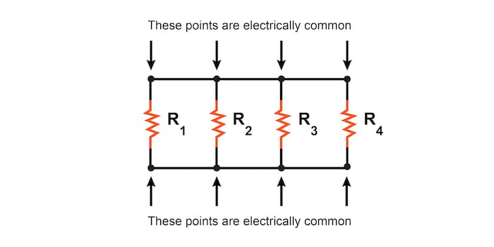
Figure 3. An example of a parallel connection of resistors.
In a purely parallel circuit, there are never more than two sets of electrically common points, no matter how many components are connected. There are many paths for current flow, but only one voltage across all components.
Introduction to Parallel Circuits—A Parallel Circuit Example
Let’s look at an example of a parallel circuit as shown in Figure 4.
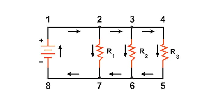
Figure 4. Example of a parallel circuit.
Again, we have three resistors, but this time there are three loops for the current to flow from the positive battery terminal back to the negative terminal:
- 1–2–7–8–1
- 1–2–3–6–7–8–1
- 1–2–3–4–5–6–7–8–1
Each individual path through R1, R2, and R3 (2–7, 3–6, and 4–5) is called a branch.
A parallel circuit’s defining characteristic is that all components are connected between the same set of electrically common points. Looking at the schematic diagram from Figure 4, we see that points 1, 2, 3, and 4 are all electrically common; so are points 5, 6, 7, and 8. All of the resistors, as well as the battery, are connected between these two sets of points. This means that the same voltage (V) is dropped across all components in a parallel circuit.
Series vs Parallel Circuit Review:
- In a series circuit, all components are connected end-to-end, forming a single path for current flow.
- In a parallel circuit, all components are connected across each other, forming exactly two sets of electrically common points.
- A “branch” in a parallel circuit is a path for electric current formed by one of the load components (such as a resistor).
Series, Parallel, and Series-parallel Circuit Related Content:
Below find more ways to learn more about series, parallel, and series-parallel circuits:
Calculators:
Worksheets:
- Series-Parallel DC Circuits Worksheet
- Parallel DC Circuits Practice Worksheet
- Series and Parallel AC Circuits Worksheet
- Series-Parallel Combination AC Circuits Worksheet
Video Lectures and Tutorials:
- Video Tutorial—Parallel Circuits
- Video Tutorial—Series Circuits
- Video Tutorial—Series-parallel Circuits
Technical Articles:
- Resistors in Parallel: Circuit Analysis with Parallel Resistance
- Resistors in Parallel: Understanding Current and Voltage in Parallel Networks


For series circuits, voltage gets dropped at each component, but the current is same for all of them, as the path is continuous. So, series circuits are also called Voltage dividers.
For parallel circuits, it’s the opposite, as voltage will flow the same in each path, the current get’s dropped/separated for each path. For that very behaviour, these circuits are also called as Current dividers.
Why do you not write the formulae 1/R =1/R1+1/R2