Facebook
 Google
 GitHub
 Linkedin
Parallel Circuits
Video Lectures created by Tim Feiegenbaum at North Seattle Community College.
When we started chapter four we mentioned that there were four basic ways to connect circuits. In 4.3 here we are going to be looking at parallel circuits which is the second major method.
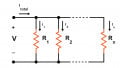
Parallel components and circuits are another fundamental way to connect electrical and electronic devices. A parallel circuit is characterized by having the same voltage across every component in the circuit and you will notice here we have a voltage source and that source is connected directly across every component. Two components are connected in parallel; both ends of each component are directly connected together. We are just looking at R1 and R2, we know they are in parallel because both ends of said components are both connected to each other and hence these two are in parallel. Likewise, if every component in a circuit is directly connected across every other component in the circuit then the entire circuit is in parallel and as you can see every single component here is directly connected across each other so we can say that this entire circuit is in parallel. Every component in a parallel circuit will have the same voltage across it and that will be out applied voltage.
The following principles apply to parallel circuits: all components will have the same voltage across them. The total current is greater than any one branch current and we will see that as we look at our circuit calculations. We will find that the total current will be the sum of all three component currents added together. The total resistance is less than any one branch resistance and what we will find is there is a rule of thumb concerning parallel circuits that if we have multiple resistances in a parallel circuit you will find that the total resistance will be less than the very smallest resistance, so total resistance is less than any one branch resistance. Total power is greater than any on component dissipation, so the total power is going to be the sum of all of the component power dissipations added together and that will be greater than any one single component dissipation.
Mathematical Relationships
Then we have some formulas, mathematical relationships in parallel circuits Kirchhoff's current law is used to analyze the circuit much as Kirchhoff's voltage law was used in series circuits. Here we have the formula for parallel resistance, we will be applying this in just a couple of moments and then here we have the current relationship, the current will be I1 + I2 + I3 etcetera. The applied voltage will be the same across V1, V2 and on and on, the power dissipation will be the sum of the power dropped across all components.
First of all let us look at the formula for parallel resistance and we talk about the parallel resistance, what we are talking about is here we have this voltage and it is connected across two components. Now this could be many components just for simplicity we are just going to deal with two to start with but what we are calculating is: What is the total resistance than this power supply sees? It sees 1K in parallel with 2K but what is that total resistance and this is the formula to calculate that.
Why don't we write out the actual values here and do a little bit of calculating? First of all let us start out with one over, and the first one is one over R1. Now R1 in this case is 1K which would be one divided by 1000. Then we are going to add that to the sum of one divided by, and the second component here is 2K, divided by 2000. We are going to add those up then we are going to do one over whatever that value is. One over 1000 that's going to be about 1000 or 0.001 and one over 2000 is going to be half of that so about 0.0005 and so roughly if we added these two together we would get about 0.0015, 15,000. Our calculation would look something like this: one over this value and that would equal our resistance.
I do not expect you to do this kind of thing in your head so let us pull up a calculator and we will look at how we would do this. First of all we want to know one over R1, so we will click in 1000 and then we have a function of one over x, so if we click on that we will see there we have 1000, that is one exponent minus three and that is equivalent to this value right here. Then we are going to be adding it to 2000 and we would do the same thing, one over x, and then let us look at the equals sign to see what the total is and that is 1.5 thousands. Remember our total resistance is going to be one over this value and so again we would do our one over x function and here we get our value of 666.66 ohms. If we were to redraw our circuit here, if we said here is out power supply and we put the resistance over here, the equivalent resistance is 666.66 ohms and our reply voltage is ten volts. That gives us our parallel resistance. That is, remember, ten volts, when it is applied to these two components that is the resistance which is felt, that is the parallel resistance.
Something that does not go into this and my real concern is that you will be able to use formula, but just as a point of reference let us take a brief look at what is we are actually looking at. If you remember in earlier chapters we looked at something called a semen and we said a semen was the reciprocal of resistance, it was one over resistance. What we are doing here when we said 1 over 1000 plus 1 over 2000 we are adding up the total semens. We got this value right here and this was actually the total semens and if you remember that resistance equals one over the semens and so we did this so we could calculate the parallel resistance, so we did one over x and that is what gave us this value. Essentially when you calculate parallel resistance what you are doing is you are adding up the total conductants and then taking the reciprocal of that total conductance indicating the resistance. Now your book does not go into this but I just wanted to give a little background on why this particular circuit works. If you do not want to know why it works that is ok but just be able to use this formula to calculate parallel resistance. Remember the thing we mentioned either in the intuitive relationships is that the parallel resistance will always be smaller than the smallest value of resistance. In this case R1 is the smallest value 1k and the parallel resistance was smaller than the smallest value of 1k.
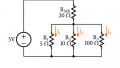
Let us go on and do a few more calculations here, we calculated the total resistance one and throw that in here again and we said our total resistance was 666.66 ohms and our applied voltage is ten volts. For the current remember current equals voltage divided by resistance so here we have an applied voltage across this component so we have ten volts divided by 1K ohm, that is going to be ten milliamps and remember we have the same ten volts across our 2K here, so that would be ten volts across 2K which would be five milliamps so our total current across both components is going to be 15 milliamps.
Another way to have done that would have involved the calculator, but remember we calculated the total resistance so we could have said ten volts divided by 666 ohms should yield 15 milliamps as well and if we were to grab the calculator real quick let us see if we can confirm that… 15 milliamps, is in fact, the answer. We calculated the current and now the applied voltage of the VA across R1 and R2 is the same thing so there is nothing profound about voltage. Power, we are going to be looking at the total power, which is going to be the sum of P1 + P2 + however many more components we have. Again we could look at the individuals first, so the individual voltage drop across the 1k was ten milliamps and this is going to be the power here. Ten milliamps times the ten volts would give us 100 milliwatts, that would be across R1 so remember ten milliamps have occurs through this component times the voltage would give us that current. Then across R2 the current was five milliamps times the applied voltage ten volts equals half of that, 50 milliwatts so we should have 150 milliwatts of power. We could have done this another way, we could have said our total applied voltage times our total current so in this case, we could have said ten volts is our applied total voltage times the total current which is 15 milliamps, 10 x 15 is going to be 150milliwatts.
That was our basic calculation addressing resistance, voltage, current and power for basic parallel circuits.
Parallel Voltage Sources
Parallel voltage sources, sometimes more power is needed in the circuit than what can be supplied by a single voltage source so what we are looking at here, let us pretend we have a voltage source and have some parallel components connected to it, let us say we can pick out a bunch of them. What we are going to find here is that the current draw across all these components is going to be quite significant and that this power supply on its own may have difficulty providing that much current so what you can do is put another power supply in here and connect it in parallel with this power supply and this could help in supplying the additional current needs of all these components. If you are going to do this it must have the same voltage, so if this is a common battery, 1.5volts and we have another 1.5volt source here, this will not be a problem and the source will continue to be 1.5volts, it just means you will have additional power to supply the need of all these components. Total volts will be the same but the current capacity will increase.
In this lesson we looked at some of the calculations concerning parallel circuits, we have calculated resistance, voltage, current and power and we looked at two different relationships in parallel circuits and we defined parallel circuits.