 Facebook
 Google
 GitHub
 Linkedin
Resistance in Parallel Networks
Parallel circuits are one of two fundamental circuit configurations we come across every day. Like a parallel universe, parallel circuits and networks can give us unexpected results. Adding more gives less, and voltage stays the same no matter what! Learn about the role resistance plays in parallel circuits for your designs and safety.
Parallel circuits are one of two fundamental circuit configurations we come across daily. Like a parallel universe, parallel circuits and networks can yield unexpected results. Adding more gives less, and voltage stays the same no matter what! Learn about resistance's role in parallel circuits for your designs and safety.
Resistors in Parallel
When using resistors, we usually focus on the fact they "resist" current and can be used to limit current to specific levels. When resistors are in a series configuration (the other main circuit configuration) shown in Figure 1, the total resistance of the circuit is the sum of the resistors:
$$R_{Total} = R_{1} + R_{2}$$
The current can be found using Ohms Law,
$$V = IR$$
Solving for I:
$$I = \frac{V}{R}$$
Once you know the current, you can find the voltage drop across each resistor. (For this discussion, we'll disregard any resistance the wire may add, as it is usually negligible compared to the resistors.)
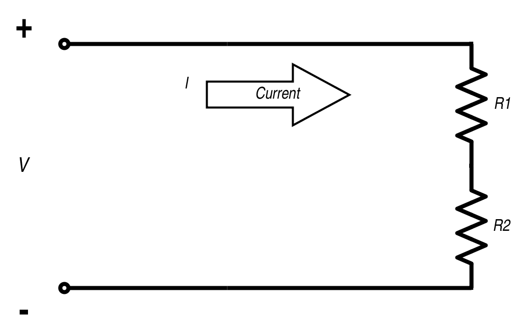
Figure 1. Series resistors RTotal = R1 + R2
Ohm's Law : $$V = IR$$
Conductance
When using resistors in a parallel circuit, we also consider their conductance. Conductance is how well current can flow through an object and is the reciprocal of resistance. Symbolized by G,
$$G = \frac{1} {R}$$
The standard unit of conductance is the Siemens (S); it was formerly known as the mho (ohm backwards) and you may still see that. While resistors are used to limit current and resist current flow, they do allow current to flow through them and they are conductors.
Parallel Resistor Circuits
You'll sometimes hear parallel resistor circuits referred to as parallel resistor networks. What's the difference? There isn't one! There is no difference between a resistor circuit and network. Networks can be more complicated, but the same equations govern the flow of current and the calculation of the total resistance.
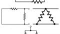
No matter how you refer to the parallel configuration, you need to have two terminals where you can measure the resistance. The resistance between these two points is the resistance of the network. Figure 2 shows a parallel resistor circuit network; Points A and B are the terminals where the total network Resistance is measured. Note the individual resistor branches all connect to the same voltage.
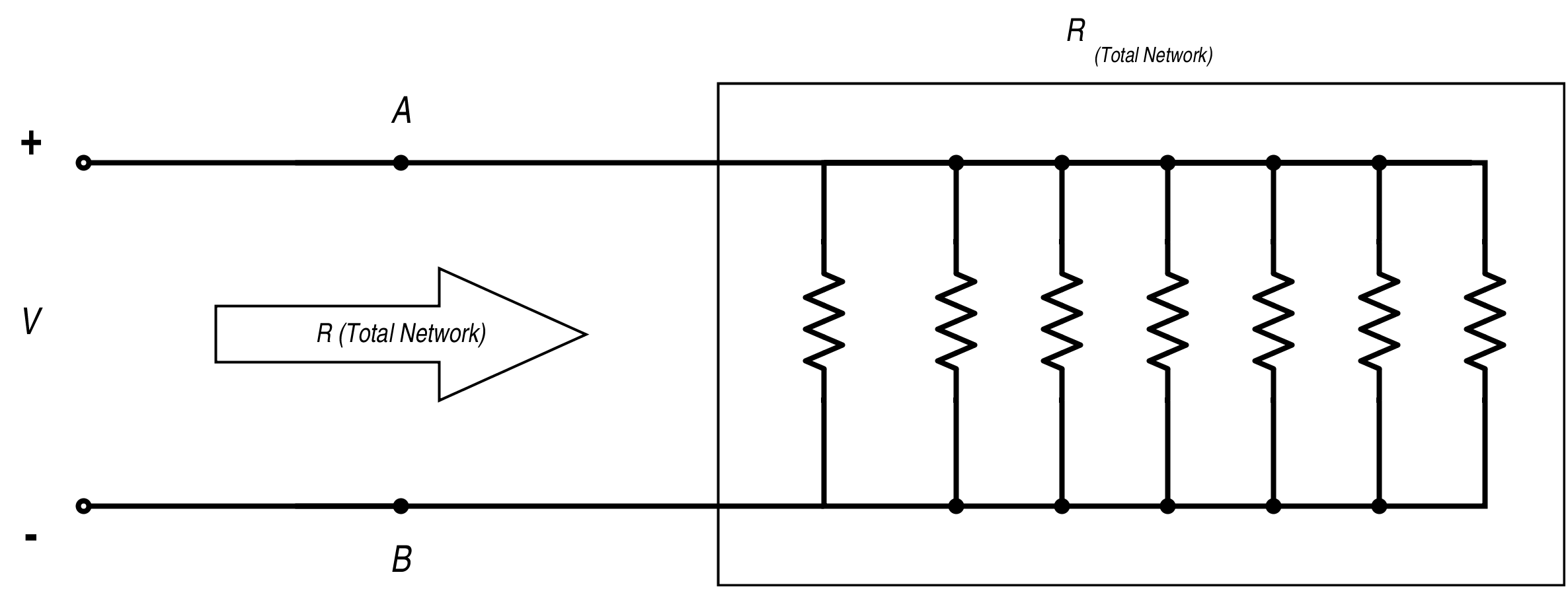
Figure 2. Parallel resistor network
Parallel Configuration
There are a few things to know that are specific to the parallel configuration:
The voltage is constant across each branch of the circuit; within each branch, Ohm's Law still holds:
$$V = IR$$
And the voltage is known for each branch: it's the same voltage for all branches. If the resistance is known, then the current through each branch can be calculated.
The total current for the circuit is the sum of the current through each branch. Kirchhoff's Current Law states that at each node (where branches section off) the current entering the node is equal to the current leaving the node. This means the total current of the circuit will equal the sum of all the currents through the individual branches.
One thing about resistors in parallel is that the resistance of the total network will be LESS than any of the resistances of the individual branches. Let's look at why:
The total resistance of the parallel circuit is determined using the following equation:
$$\frac{1}{R _{total}} = \frac{1}{R1} + \frac{1}{R2} + \frac{1}{R3} + … \frac{1}{Rn}$$ [Equation 1]
Resistance is the reciprocal of conductance, as we mentioned before, so Equation 1 calculates the conductance of a parallel circuit. To find the resistance, we take the reciprocal. Each resistor added in parallel to the circuit adds a new branch to the circuit, which is a new path for the current to take, and it becomes easier for the current to flow through the circuit. It's like when a two-lane highway becomes three lanes: the cars have a new lane to use, the overall traffic is less congested, and it's easier to get where you are going.
You deal with parallel circuitry daily: house wiring is in a parallel configuration, so you can independently switch lights and appliances on and off. And that is one of the best reasons to use parallel circuits: they allow independent control.
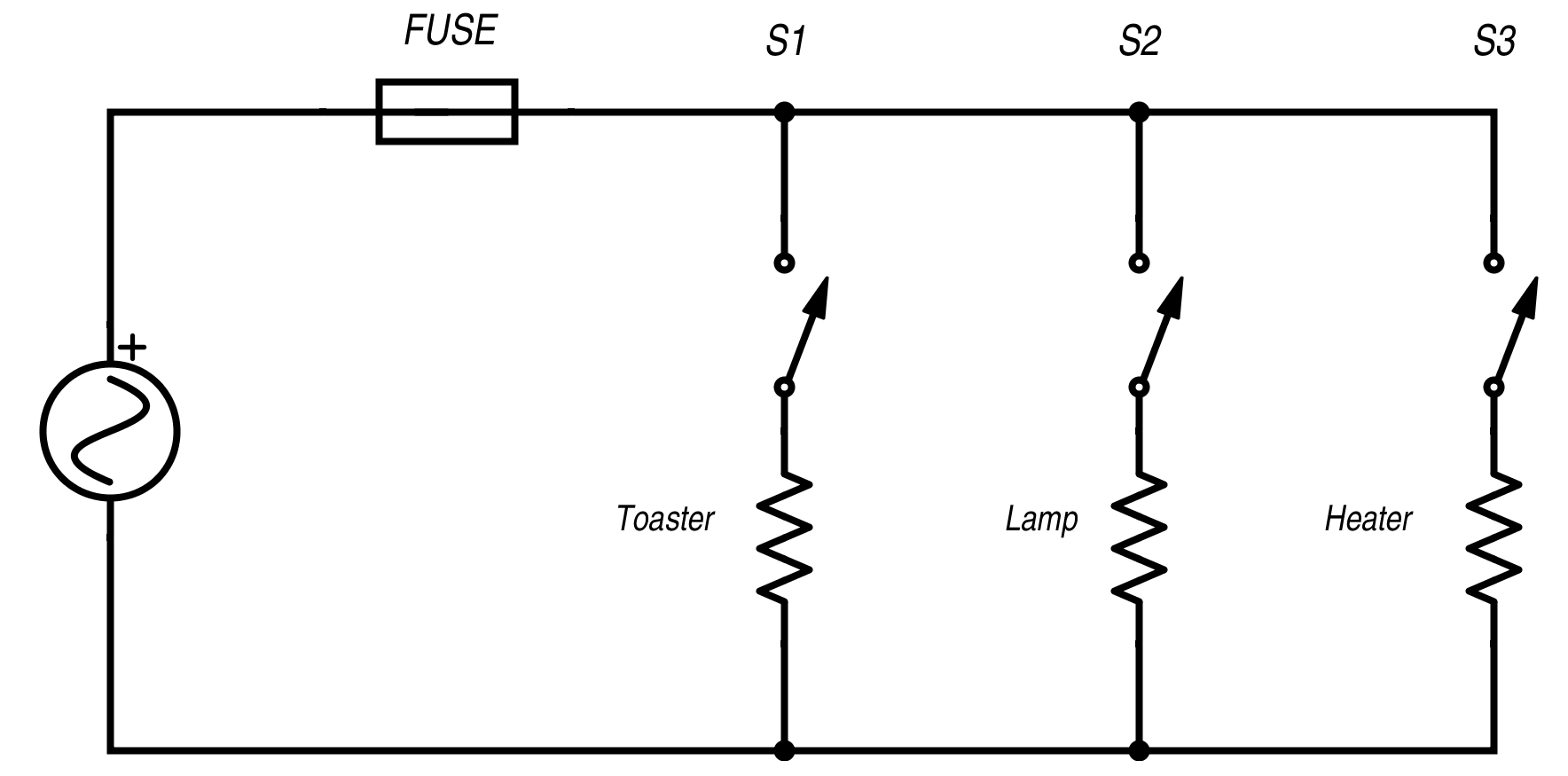
Figure 3. Home wiring of parallel circuits
Let's look at some examples:
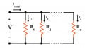
In Figure 4, we have two 30 Ohm Resistors in Parallel.
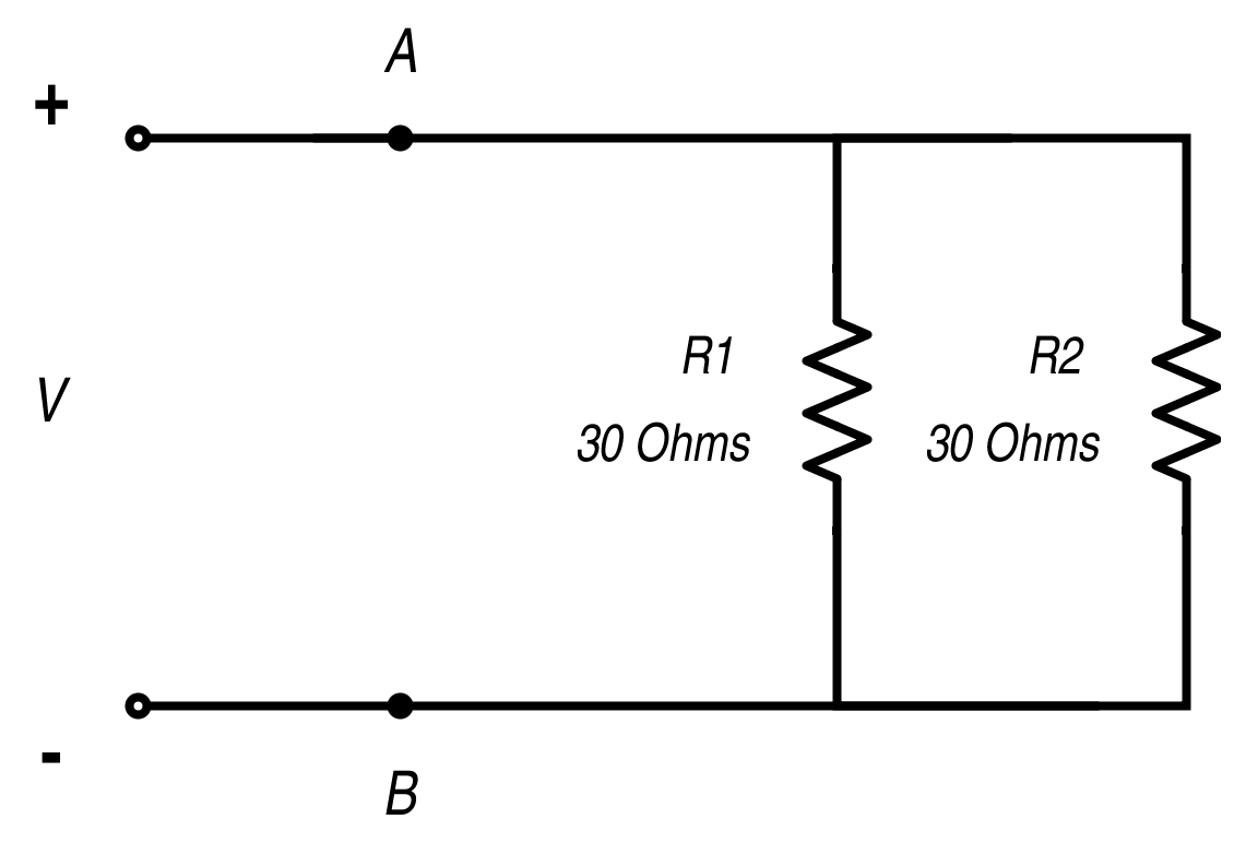
Figure 4. Parallel resistors
The voltage across the two resistors is the same. If Voltage V = 15 Volts, 15 volts will be across R1 and R2. The total resistance of the circuit, measured across points A and B, is calculated according to the equation:
$$\frac{1}{R_{Total}}= \frac{1}{R1}+ \frac{1}{R2}$$
For R1 = R2 = 30 Ohms, the equation becomes:
$$\frac{1}{R_{Total}}=\frac{1}{30\Omega}+\frac{1}{30\Omega }= \frac{2}{30\Omega }$$
$$30\Omega = 2 R_{Total}$$
$$\frac{30\Omega }{2}= R_{Total}$$
$$\underline{R_{Total}= 15\Omega}$$
So, two resistors of the same value present a total network resistance of ½ their value.
Looking at the current flow through the circuit: when both branches present the same resistance, half the current will go through the branch with R1, half will go through R2 and the resistance has effectively been cut in half.
For cases when R1 and R2 are not equal, the total network resistance is calculated the same way, and the current for each branch is dependent on the voltages across the branch and the individual resistors.
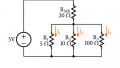
For instance, if R1 is 500 Ohms and R2 is 1K Ohms, the total resistance of the network is:
$$\frac{1}{R_{Total}}= \frac{1}{500\Omega }+\frac{1}{1000\Omega }= \frac{3}{1000\Omega }$$
$$(1)(1000\Omega) = 3 R_{Total}$$
$$\frac{1000\Omega }{3}= R_{Total}$$
$$\underline{R_{Total}= 333.33\Omega}$$
A quick check for your calculations is that R(Total Network) should be less than any of the resistance values for the individual branches.
A parallel circuit with three resistors of 30 Ohms each is shown in Figure 5.
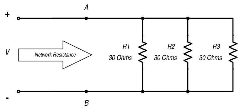
Figure 5. Three resistors in parallel
$$\frac{1}{R_{Total}} = \frac{1}{R1} + \frac{1}{R2} + \frac{1}{R3} $$
The equation for the Total Resistance is:
$$\frac{1}{R_{Total}}= \frac{1}{30\Omega }+\frac{1}{30\Omega }+\frac{1}{30\Omega }$$
$$\frac{1}{R_{Total}}= \frac{3}{30\Omega }$$
$$30\Omega= 3 R_{Total}$$
$$\frac{30\Omega }{3}= R_{Total}$$
$$\underline{R_{Total}= 10\Omega}$$
When another resistor was added in parallel to the circuit in Figure 4, giving the circuit in Figure 5, the total resistance of the network became less. Because the voltage is the same and each branch has the same resistance, the current flow through each branch equally. Equation 1 can be used for any number of resistors to calculate the total resistance.
Referring to the house wiring diagram in Figure 3, the parallel circuitry allows the toaster, lamp, and heater to be turned on and off individually without affecting the others. As more branches are added-- that is, as you turn on more equipment wired into the same parallel circuit--the total resistance becomes less and less, and with the resistance falling, the current builds Ohm's Law:
$$I = \frac{V}{ R}$$
The lower the total network resistance becomes, the larger the current becomes. If enough equipment is turned on to cause the current to become greater than the fuse or circuit breaker rating, the fuse blows, and the circuit breaker trips. Fuses and circuit breakers provide a safety feature for your house wiring. Too much current trips fuses and circuit breakers to create an open circuit for all branches, hopefully preventing overheating and fires.
The takeaway for resistors in parallel circuits is that the total network parallel resistance is calculated by Equation 1, and according to that equation, the more resistors in parallel, the lower the total network resistance.
The voltage across each branch is constant and the total current is the sum of all the currents through the individual branches.


A good piece for reading. But definition about r<a >resistors in parallel</a>is missing.