Facebook
 Google
 GitHub
 Linkedin
Introduction to Clock and Data Recovery
Learn how PLLs enable communication in which a clock signal is not transmitted with the data. We’ll look specifically at return-to-zero (RZ) and non-return-to-zero (NRZ) data formats.
Many systems use asynchronous communication, meaning data is transmitted without a corresponding clock signal. In these cases, the receiver must determine the correct timing to decode the incoming bit stream. The process of extracting a clock from the incoming data stream and using it to sample the bits at the correct instants, ensuring accurate data interpretation, is known as clock and data recovery (CDR).
In this article, we'll explore how CDR extracts the clock signal from the return-to-zero (RZ) and non-return-to-zero (NRZ) data formats. Before we can do so, however, we need to familiarize ourselves with the basic characteristics of asynchronous communication and CDR. To add context, we'll begin with a brief discussion of a system architecture that doesn't use CDR: the forwarded-clock system.
Forwarded-Clock Systems
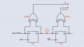
A forwarded-clock system is a high-speed signaling architecture where the transmitter (TX) sends a clock signal alongside the data to help the receiver (RX) synchronize and sample the data accurately. The receiver aligns its sampling to the incoming clock, eliminating the need for complex CDR circuits. Such a system is illustrated in Figure 1.

Figure 1. A forwarded-clock system. Image used courtesy of A. Amirkhany
While this scheme can simplify the receiver and reduce its power consumption, it necessitates an additional lane for the clock signal. Since the clock and data travel along separate paths, it's essential to minimize skew (the timing misalignment caused by unequal trace delays). To effectively address this challenge, the circuit components and PCB traces for both the data and clock paths should be closely matched. This enhances jitter tracking between them.
Asynchronous Communication
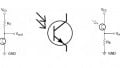
While forwarded-clock systems are commonly used in interfaces such as SPI, UART, DDR2-5, and HDMI, the requirement for a dedicated clock lane makes this method impractical for some applications. This is where asynchronous communication systems come in. An example is shown in Figure 2.
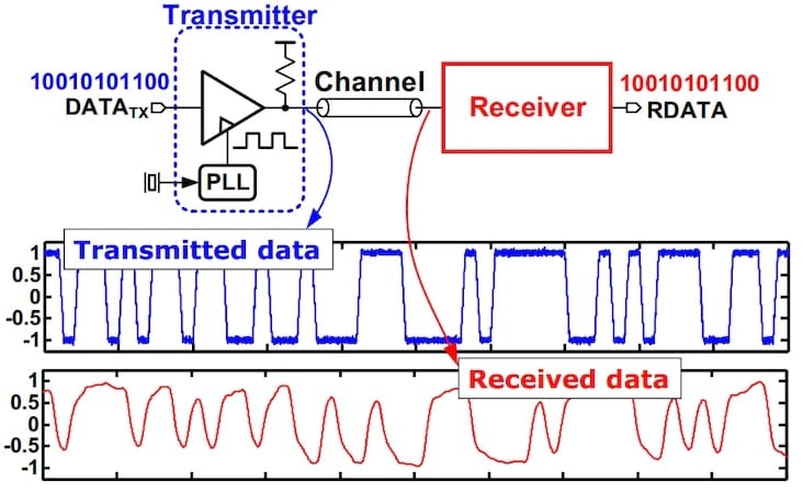
Figure 2. In many applications, the data bits are transmitted without the corresponding clock. Image (adapted) used courtesy of Pavan Hanumolu
The receiver must interpret the incoming bits without having the clock signal that the transmitter used to generate them. Lacking timing information, the input waveform looks like a random stream of bits, making its correct interpretation challenging. For example, the waveform illustrated in Figure 3 can be read as either 10110 or 1100111100 depending on the sampling frequency employed.
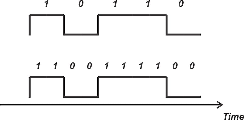
Figure 3. Two different interpretations of the same input waveform. Image used courtesy of Steve Arar
But how can the receiver extract the clock from a random stream of binary bits? To answer this, we need to consider the spectral characteristics of the data.
Spectral Characteristics for Effective Clock Extraction
Consider the hypothetical data spectrum shown in Figure 4.

Figure 4. The hypothetical spectrum of a bit sequence. Image used courtesy of Steve Arar
Assume the above spectrum corresponds to a random bit sequence generated using a clock frequency of fb. Is it possible to use a narrowband filter to isolate the clock signal from the other spectral components?
The answer is no! The amplitude at fb is not significantly different from the surrounding frequency components. Consequently, a practical filter would permit all components near fb that lie within the filter's passband to be present at the output, making it impossible to isolate the clock signal. The given spectrum is therefore unsuitable for reliable clock recovery.
However, if the input data spectrum contains an energy impulse at the clock frequency, we may be able to employ various signal processing techniques to extract the clock signal. This is shown in Figure 5.

Figure 5. A data spectrum that includes an impulse at the clock frequency facilitates the process of clock recovery. Image used courtesy of Steve Arar
In the above spectrum, the energy at fb is significantly higher than the nearby components. Because of this, it's possible to generate a low-noise periodic clock from the random stream of bits.
There are multiple ways to encode a given bit sequence, each of which has different spectral characteristics. Now that we understand the necessary characteristics for clock recovery, let's explore the spectra associated with two common data encoding techniques: RZ and NRZ.
RZ Data
Figure 6 demonstrates the return-to-zero (RZ) method for the bit sequence 1011001.

Figure 6. RZ data and the corresponding clock for its sampling. Image used courtesy of Steve Arar
In this encoding scheme, a binary 1 is represented by a logic HIGH that drops to zero before the bit period ends, while a binary 0 is represented by a logic LOW. The signal therefore goes LOW between adjacent 1s, hence the name return-to-zero.
In the above figure, Tb signifies the time span of a symbol, with b referring to baud. Baud is a unit of measurement for the number of signal changes, or symbols, transmitted per second in a communication channel. In our discussion, the baud rate equals the bit rate. However, this is not always the case. Some encoding schemes embed multiple bits in each symbol.
Figure 7 shows the typical spectrum for this type of data encoding.

Figure 7. Typical spectrum of RZ data. Image used courtesy of Steve Arar
The spectrum of the RZ data includes a distinct line component (an impulse of energy) at the baud rate (fb = 1/Tb). The impulse at fb remains present even if the signal experiences lowpass filtering, regardless of whether filtering is intentional or a consequence of the signal traveling through a transmission medium. Figure 8 illustrates the effect of filtering on the RZ data in the time and frequency domains.

Figure 8. Typical RZ data spectrum in its original form (a) and after lowpass filtering (b). Image used courtesy of Steve Arar
When RZ data passes through a lowpass filter, the impulse at frequency fb may experience attenuation due to the filter's response. However, assuming that the filter is sufficiently wideband, the time-domain waveform will return to zero between adjacent 1s, as shown above. In this case, the line component at fb will still be present in the signal spectrum.
A bandpass filter can be employed to isolate this component from adjacent frequency elements for CDR purposes. It's essential for this filter to possess a very narrow bandwidth and a center frequency accurately aligned with fb. This type of filter can be realized using a PLL, as illustrated in Figure 9.

Figure 9. A PLL can be used to isolate a line component in the signal spectrum. Image used courtesy of Steve Arar
The PLL must lock to the impulse at fb while rejecting the unwanted frequency components that surround it. It's worth noting that a PLL's bandwidth can be a very small fraction of its input frequency, yielding an extremely high-Q response.
NRZ Data
Figure 10 illustrates an alternative data format for the bit stream 1011001.

Figure 10. NRZ data alongside the corresponding clock for its sampling. Image used courtesy of Steve Arar
With this encoding scheme, known as the non-return-to-zero (NRZ) format, the signal level remains constant during each bit period. This leads to improved bandwidth efficiency, since it avoids the additional transitions that the RZ method necessitates.
The downside of NRZ data is that it's difficult to synchronize. To help us understand the synchronization issue, Figure 11 shows the typical spectrum of the NRZ data format.

Figure 11. Typical spectrum of NRZ data. Image used courtesy of Steve Arar
The spectrum of NRZ data doesn't have a line component at the baud rate (fb). In fact, the spectrum goes to zero at integer multiples of fb, meaning that it carries no energy at these frequencies. Therefore, unlike the RZ format, a PLL cannot directly be used to extract the clock from NRZ data.
Using Edge Detection for Clock Recovery From NRZ Data
To recover the clock from NRZ data, we can first apply it to an edge detector circuit such as the one in Figure 12(a).

Figure 12. Circuit for edge detection (a) and resulting waveforms (b). Image used courtesy of Steve Arar
Edge detection alters the spectrum of NRZ data, introducing an impulse frequency component at the baud rate (fb). Having generated this impulse, we can now apply a PLL to separate it from the surrounding frequency components, enabling the production of a low-noise clock.
Some sources describe this circuit as one that transforms NRZ data into RZ-like data. However, it doesn't genuinely generate RZ data. For example, when an NRZ data sequence consisting of consecutive 1s is input into the circuit, the output will not alternate between HIGH and LOW levels between adjacent 1s, as would be expected in RZ format.
To learn how edge detection produces the frequency component at fb, you can refer to Section 13.3 of Behzad Razavi's book, "Design of CMOS Phase-Locked Loops From Circuit Level to Architecture Level."
Wrapping Up
After introducing the concept of CDR, this article explored the time and frequency domain characteristics of the RZ and NRZ data formats for asynchronous communication. As we learned, PLLs play an essential role in CDR applications. In the next article, we'll focus on the design of PLLs for clock recovery.
Because PLLs employed in CDR must process random input data to produce a periodic clock, we'll see that only certain types of phase detectors can be used for this purpose. We'll discuss one of these, the Hogge detector, in detail.
Related Content